Manual 2100-495A
Page
6 of 21
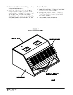
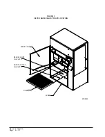
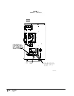
FIGURE 1
INTAKE HOOD ASSEMBLY
16. Disconnect the wires connected in Step 10 if other
control options are to be used.
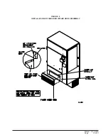
17. Replace the lower service access panel with the
new panel provided. Attach air intake hood with
screws provided. (See Figure 9.) Be sure to insert
the top flange of the air intake hood into and
through the slot in the service door and between the
door and insulation to prevent bowing of the door.
18. Close front door.
19. Apply Certification label, included with Installation
Instructions, next to unit Serial Plate.
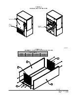
20. Assemble exhaust blower enclosure as shown in
Figure 2A and install on unit as shown in Figure 4
(with screws provided).
21. Ventilator is now ready for operation.
Содержание WFERV-A-X
Страница 10: ...Manual 2100 495A Page 10 of 21 FIGURE 5 INSTALLATION OF WFERV...
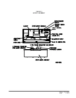
Страница 11: ...Manual 2100 495A Page 11 of 21 FIGURE 6 WFERV ASSEMBLY...
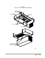
Страница 13: ...Manual 2100 495A Page 13 of 21 FIGURE 8 INSTALLATION OF FRESH AIR INTAKE HOOD ASSEMBLY...
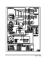
Страница 18: ...Manual 2100 495A Page 18 of 21 FIGURE 10 THERMOSTAT WIRING DIAGRAM...
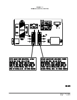
Страница 19: ...Manual 2100 495A Page 19 of 21 FIGURE 11 TERMINAL BLOCK LOCATION...
Страница 20: ...Manual 2100 495A Page 20 of 21 FIGURE 12 HUB ASSEMBLY WITH BALL BEARING...
Страница 21: ...Manual 2100 495A Page 21 of 21...


