


R9001440/9
GRAPHICS
Uniformity Adjustments
Date:10/02/2000
6300
13
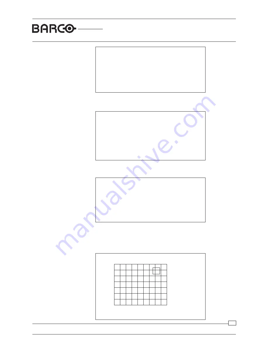
Uniformity Correction Adjustments
Red:64
Green:62
Blue:63
Reading settings
Red
Offset
Commands:
C: select active color
V: enter Value
I: Initialize total grid
+: increase value
-: decrease value
<cursor>: Move a grid
<enter>: Send to projector
R: Read proj. uniformity
O: Open and Read file
S: Save on file
D: Store to default
F: restore Factory Default
A: Automatic adjustment
M: Top-Bot Lft-Rght corr.
Q: Quit Program
ç
ç
Uniformity procedure V1.0
Step1: Input projector data
Color meter must be connected to the computer.
Serial port for communication with colormeter?
0: No Color Meter connected
1: COMM1
2: COMM2
Your choice:_
Enter the PC Serial COMM-port for communication with the colormeter. According to
the diagram on page10, COMM1 port of the computer is connected to the Colormeter,
so type in number 1 and press
ENTER
.
Uniformity procedure V1.0
Step1: Input projector data
Color meter used:
1: LMT
2: THOMA TMF
3: Minolta CS1000
Your choice:_
Uniformity procedure V1.0
Step1: Input projector data
Checking projector and colormeter
Data stream.................................................................
Result..........................................................................
Retry(R), Continue(C) or Abandon(A): _
If no failure has been detected during checking the projector and the colormeter, type
in C (continue) and press
ENTER
to continue the uniformity adjustment procedure.
On the PC, a grid will be displayed with 17 x 13 adjustment points. For the Reality
projectors this grid consists of 11x17 points
.
Type in type of used color meter and press ENTER. The program will switch the
projector to a full projector white image and read the color meter output (if connected)
to check the connections.


