background image

601

426-03

F70 Series

115

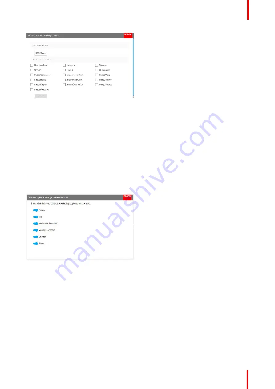
Image 9-5: Reset menu

2.

Navigate to the checkbox next to the settings that need to be reset and press

OK

.

Multiple selections are possible.

3.

Select

RESET

and press

OK

to reset all selected settings.

9.6 Lens Features

About

In order to prevent unintentional lens adjustments, especially after e. g. a completed setup and adjustment,
there is a possibility to disable certain lens adjustment functions. These functions are directly accessible via
the remote control, and can by that easily be adjusted by accident.

Enter the menu shown below, and disable the desired functions by toggling the desired buttons. The menu
below shows all lens options in enabled position.

Image 9-6

9.7 Controlling the backlight of the LCD Display

What lighting can be controlled?

You can choose how quickly the backlight of the LCD turns off. You can select one of the default values, or
enter a custom value.

Alternatively, you can turn on

Stealth Mode

instead. By activating this mode, both the backlight of the LCD as

well as the backlight of all the buttons of the keypad will be permanently disabled.

How to control

1.

In the main menu,

System Settings

Backlight

.

System settings menu

Содержание F70 - 4K6

Страница 1: ...ENABLING BRIGHT OUTCOMES User Manual F70 Series...

Страница 2: ...drikstad AS Habornveien 53 N 1630 Gamle Fredrikstad Norway Support fre barco com www barco com Registered address Barco NV President Kennedypark 35 8500 Kortrijk Belgium www barco com en support www b...

Страница 3: ...or modifications not expressly approved by the party responsible for compliance could void the user s authority to operate the equipment Trademarks Brand and product names mentioned in this manual ma...

Страница 4: ...chaser or a third party carries out modifications or repairs on goods delivered by Barco or if the goods are handled incorrectly in particular if the systems are operated incorrectly or if after the t...

Страница 5: ...Maintenance 29 2 3 LED Status Light 29 2 4 Power on Standby button backlight indications 29 2 5 LCD panel 29 2 6 Local keypad 30 2 7 Remote Control 31 2 7 1 Remote control Battery installation 31 2 7...

Страница 6: ...HDBase T 62 5 1 3 Control interfaces 62 5 1 3 1 RS 232 62 5 1 3 2 LAN Ethernet 63 5 1 3 3 USB A port 63 5 2 Power up the projector 63 5 3 Power down the projector 63 5 4 Power mode transitions 64 5 4...

Страница 7: ...the system 104 8 5 3 Adjustment Procedure 104 8 5 4 Black Level Adjustment 105 8 5 5 Black Level Files 106 8 5 6 Blend Files 107 8 5 7 Advanced Blend 108 8 6 Illumination 108 8 7 CLO constant light o...

Страница 8: ...601 426 03 F70 Series 8 14 3 FS70 4K6 132 14 4 FS70 W6 134...

Страница 9: ...that the content is applicable for the following products F90 W13WUXGA F90 4K13 4KUHD WQXGA F70 4K6 F70 W6 Defining the GP6 platform The F90 series products in general are all products within the Bar...

Страница 10: ...rized by Variance Number 2016 V 0144 effective March 6 2017 Do not stare into Beam This projector is Risk Group 2 RG2 according to IEC EN 62471 5 This projector may become Risk Group 3 RG3 when an int...

Страница 11: ...user manual for the lens list and hazard distance before operation Such combination of projector and lens are intended for professional use only and are not intended for consumer use FOR PROFESSIONAL...

Страница 12: ...changed if they have become visibly damaged for example with cracks or deep scratches to such an extent that their effectiveness is impaired To prevent fire hazard Barco projection products are design...

Страница 13: ...til it has been checked by Barco authorized service personnel Do not block the projector cooling fans or free air movement around the projector Minimum safety distance to the exhaust area of the unit...

Страница 14: ...e a RG3 laser Product dependent on which lens used This projector may become Risk Group 3 RG3 when an interchangeable lens with throw ratio greater than 4 7 is installed For Northern America installat...

Страница 15: ...the above limits for cinema like environments do not apply The relevant minimum separation height is 2 5m 8 2 ft by the FDA CDRH Non cinema like environments require 2 5 meter 8 2 ft separation height...

Страница 16: ...applicable exposure limit on the cornea or on the skin The light beam is considered to be unsafe for exposure if the distance from a person to the light source is less than the HD Restriction Zone RZ...

Страница 17: ...he beam areas closer than any NOHD In the enclosed projection area the combination of two restricted zones are relevant The restricted zone of the projected beam toward the screen taking into account...

Страница 18: ...4 0 6 0 8 1 1 2 1 4 1 6 1 8 0 5 0 9 1 3 1 7 2 0 2 3 2 7 3 1 3 5 3 9 4 3 4 7 5 1 5 5 5 9 6 3 6 7 7 1 7 5 Hazard Distance m Throw Ra o Hazard Distance Thermal Acidental Exposure Image 1 5 Hazard Distan...

Страница 19: ...anual For F90 series FDA Label THIS PRODUCT IS IN CONFORMITY WITH PERFORMANCE STANDARDS FOR LASER PRODUCTS UNDER 21 CFR 1040 EXCEPT WITH RESPECT TO THOSE CHARACTERISTICS AUTHORIZED BY VARIANCE NUMBER...

Страница 20: ...ODUCT RG2 IEC EN 62471 5 F90 EMC Label This Class A digital apparatus complies with Canadian ICES 003 Cet appareil numerique de Ia classe est conforme Ia norme NMB 003 du Canada CANADA This device com...

Страница 21: ...duct shall be recycled properly It can be disassembled to facilitate proper recycling of it s individual parts Consult your dealer or relevant public authority regarding drop off points for collection...

Страница 22: ...table is prepared in accordance with the provisions of SJ T 11364 O GB T 26572 O Indicates that this toxic or hazardous substance contained in all of the homogeneous materials for this part is below t...

Страница 23: ...Hazardous Substances or Elements Pb Hg Cd Cr6 PBB PBDE Printed Circuit Assemblies X O X O O O External Cables X O O O O O Internal wiring X O O O O O Lensholder X O O O O O Laser X O O O O O Chassis O...

Страница 24: ...this part is above the limit requirement in GB T 26572 1 10 Contact information Barco contact information Registered office address President Kennedypark 35 8500 Kortrijk Belgium Contact address Bene...

Страница 25: ...ipment Warning This equipment is compliant with Class A of CISPR 32 In a residential environment this equipment may cause radio interference Class A ITE Information Technology Equipment Warning This i...

Страница 26: ...601 426 03 F70 Series 26 Safety...

Страница 27: ...nd Maintenance LED Status Light Power on Standby button backlight indications LCD panel Local keypad Remote Control Projector Address Connector panel Color Wheels Optional Accessories 601 426 03 F70 S...

Страница 28: ...age 2 1 Projector Items Overview 7 6 3 5 1 5 2 4 9 8 Image 2 2 1 1 LED Warning Indicator 1 2 Adjustable Feet 1 3 Lens 1 4 Lens Holder 1 5 IR Receiver For receiving remote control signals 1 6 LCD Displ...

Страница 29: ...will again go to critical error status By high temperature the projector can be restarted when it has cooled down and the temperature is back within the normal operating limitations 2 4 Power on Stand...

Страница 30: ...l keypad About The Keypad gives direct access to several functions in addition to access to the menu system The keypad and remote control functions are equal The keypad has a back light that can be sw...

Страница 31: ...the navigation keys to manage and confirm actions 2 7 Remote Control 2 7 1 Remote control Battery installation Where to find the batteries for the remote control The batteries are not placed in the re...

Страница 32: ...Remote control protocol setup About the used protocol The protocol is the code send out by the remote control when a button is pressed Depending on this code the projector can decode the signals The...

Страница 33: ...hile entering values 4 Touch Panel On Off Not in use 17 Macro button Not in use 5 OSD On Off 18 Menu Back 6 Lens Zoom 19 Default button Not in use 7 Lens Shift 20 Lens Focus 8 Menu Activation 21 Real...

Страница 34: ...This function are for disabling the IR sensors for the remote control Either front or rear or both Image 2 9 Select the menu path Home System Settings Communication IR control Select which sensors to...

Страница 35: ...as its own address Set up an individual Projector Address The set up of a projector address can be done via the software Projector controlling When the address is set the projector can be controlled n...

Страница 36: ...These connectors can also be used to form one uniform image by feeding half of the image into each connector HDCP compliant for sources up 165 Mhz HDMI 1 Standard HDMI 2 0 For Projector Input HDBaseT...

Страница 37: ...tion R9801195 F90 flight case Image 2 11 The F70 Flight Case is a custom designed container that is suitable for shipping the projector including flight frame signal and power cords and up to two lens...

Страница 38: ...601 426 03 F70 Series 38 Getting to know the projector...

Страница 39: ...39 About Overview Approved Lenses Lens range Replace a lens Lens shift Adjust zoom and focus Adjust Iris 601 426 03 F70 Series Lenses 3...

Страница 40: ...approved approved R9801295 FLD 0 65 1 EN47 approved approved PN_EN58 FLD 0 28 1 EN58 approved approved This projector may become Risk Group 3 RG3 when an interchangeable lens with throw ratio greater...

Страница 41: ...6 2 32 1 EN11 2 1 2 52 Yes 2 1 6 5 1 45 33 2 48 1 2 0 15 FLD Lens 0 74 1 EN12 2 1 Yes 2 1 6 5 16 35 0 5 5 FLD Lens 1 24 1 6 1 EN13 2 1 2 22 Yes 2 1 6 5 1 3 25 59 33 24 1 0 15 FLD Lens 2 37 3 79 1 EN14...

Страница 42: ...6 1 WQXGA R9801211 3 08 kg FLD Lens 0 75 1 13 1 EN45 0 75 1 13 1 WUXGA 0 8 1 21 1 WQXGA R9801220 3 04 kg FLD Lens 0 75 1 13 1 EN46 0 75 1 13 1 WUXGA 0 8 1 21 1 WQXGA R9801221 3 14 kg FLD NV Lens 0 8...

Страница 43: ...ned to prevent damage to the lens board while providing an easy and stable lens change procedure The lens lever located at the bottom of the lens mount slides between two positions far left default po...

Страница 44: ...rojector lens mount 4 Replace with another lens or install the projector lens cap Image 3 5 3 4 Lens shift General Use the Remote control or the keypad on the Projector to adjust the lens shift mechan...

Страница 45: ...E N43 E N44 E N45 E N46 E N47 Iris Zoom Focus For best results lens adjustments should be done in the following order zoom focus and then iris where applicable 3 6 Adjust Iris General Iris controls t...

Страница 46: ...601 426 03 F70 Series 46 Lenses...

Страница 47: ...ine Likewise any images or graphical representations shown here are for illustrative purposes only If you require further information and assistance during the installation process contact a qualified...

Страница 48: ...lude environmental conditions Failing to follow the terms and conditions outlined in this chapter can result in loss of product warranty The table below summarize the physical environments in which th...

Страница 49: ...e Barco Sales and Service office or your preferred Barco agent of the damage as soon as possible Box Contents Your projector box should contain the following Projector unit Power cord suitable for reg...

Страница 50: ...imitations necessitate their use make sure that the extension cord has adequate surge protection and meets all electrical requirements of the connection Keep the projector away from equipment that emi...

Страница 51: ...e feet in either direction left or right allows you to fine adjust the projector position for precise vertical mechanical alignment Raise Lower Image 4 2 Mounting to a ceiling 1 Install the projector...

Страница 52: ...3 Item Thread Dimension Max Hole Depth Application 1 M6 15mm Anchorpoint Ceiling Rig Mount 4 7 Throw distance Calculate the installation throw distance Throw is the distance D measured from your proje...

Страница 53: ...1 2 0 5 5 m FLD Lens 1 24 1 6 1 EN13 1 0 15m FLD Lens 1 16 1 EN15 1 5 15m FLD Lens 1 6 2 32 1 EN11 2 0 15m FLD Lens 2 37 3 79 1 EN14 3 0 30m FLD Lens 3 80 6 50 1 EN16 4 0 40 m Image width m 12 00 11 0...

Страница 54: ...3 00 4 00 4 50 5 00 5 50 6 00 6 50 7 00 7 50 3 50 0 00 Image height F L D L e n s 0 8 1 E N 4 2 0 7 7 m FLD Lens 1 7 2 5 1 EN41 1 5 15m FLD Lens 2 5 4 6 1 EN44 2 5 25 m FLD Lens 1 2 1 7 1 EN43 1 5 15...

Страница 55: ...e 4 6 4 8 Scheimpflug Boresight adjustment What is Scheimpflug The lens holder has to be adjusted so that the sharp focus plane of the projected image falls together with the plane of the screen Fp1 F...

Страница 56: ...s Masking will be required to solve the distortion The disadvantage of Masking is loss of content Therefore it is strongly recommended to place the projector in parallel with the projection screen and...

Страница 57: ...side Scheimpflug adjustment screw reference 2 until the test image in the top left side of the screen is in focus Use a size 4 hex key to do this Note This process may cause the other areas of the im...

Страница 58: ...play 6 Test the focus by zooming out minimum image size on screen and then zooming in again Verify the image is still sharp If there are any deviations to sharpness repeat steps 2 to 6 until the image...

Страница 59: ...jector setup when the physical installation process is complete Overview Projector source and control connections Power up the projector Power down the projector Power mode transitions Power modes Cus...

Страница 60: ...ctor is 2x Dual Link DVI I DVI D functionality 2x DisplayPort 1 2 1x HDMI 2 0 1x HDBaseT 1x 3G SDI 5 1 2 Connector specifications Overview DVI I Display Port 1 2 HDMI 2 0 3G SDI HDBase T 5 1 2 1 DVI I...

Страница 61: ...3 HDMI 2 0 Specifications Regarding HDMI 2 0 The decryption protocol HDCP 2 2 are enabled and valid in this unit Parameter Value Connector Standard HDMI Signal characteristics Digital TMDS Max cable l...

Страница 62: ...h Yes from Source to Projector IR Extension Not Supported RS 232 Extension Not Supported 10 100Mbps Ethernet Pass Through Not Supported Fallback to 100BaseTx IEEE 802 3u Not Supported USB Over Centre...

Страница 63: ...nnect the line cord to the projector 2 Plug the 3 pronged cord into a grounded AC outlet The projector will begin warming up and the backlight of the Standby power button are flashing white 3 When the...

Страница 64: ...ote On Off button 5 4 2 Power on projector If not already connected connect the female side of the power cord with the power input socket of the projector For more details see section dedicated to the...

Страница 65: ...g fans pumps go down except for a very small wake up controller The Power on off button will FLASH WHITE every second 5 4 6 Going from ECO to ON Description Press the Power on off button on the projec...

Страница 66: ...ccess levels Standard User and Power User In addition there is a Service user access for certified Service personnel A standard user has access to all projector functionality and OSD menu items A powe...

Страница 67: ...ep will equal 10 of the total value To enter the value as a direct number press ENTER input the digit s and then Press ENTER again to execute and exit cursor mode e g ENTER 79 ENTER Changes to values...

Страница 68: ...601 426 03 F70 Series 68 Getting started...

Страница 69: ...Enables either via the source menu or the shortcut key By navigate through the Home Source menu it will be visible also on the OSD By using the shortcut key the menu occurs only on the LCD display Ov...

Страница 70: ...isplayport Columns Dual Displayport Sequential DVI 1 DVI 2 Dual DVI Columns Dual DVI Sequential HDBaseT HDMI SDI 6 2 Connector Settings About Connector Settings The Connector Settings menu allows you...

Страница 71: ...ct Connector Settings Image 6 3 Source menu Connector Settings The available input connectors are displayed Image 6 4 Select source 4 Select the desired connector The Connector Settings menu for this...

Страница 72: ...ome Source Dual input modes There are four ways to connect dual input Dual Displayport Columns Dual Displayport Sequential Dual DVI Columns Dual DVI Sequential For Images to be displayed in this mode...

Страница 73: ...Series 73 Dual Column Input 2 Dual Column Input1 2400 2400 1920 1920 3840 Image 6 6 Dual Column Setup Dual Sequential Input 2 Dual Sequential Input1 2400 3840 2400 3840 Image 6 7 Dual sequential setu...

Страница 74: ...601 426 03 F70 Series 74 Source menu...

Страница 75: ...nu is shown below The OSD menu is shown in the different topics below and is visible in the lower left corner of the screen The operation of the menus can be done with both the remote control or the a...

Страница 76: ...601 426 03 F70 Series 76 Image 7 2 Image sub menu visible on the LCD Image menu...

Страница 77: ...rpness and Gamma by using the up and down arrows on the remote control or keypad 7 2 Brightness About Image Brightness The brightness function is used to adjust the black level in the input picture It...

Страница 78: ...ges eg a table with text and borders In a natural picture high sharpness can be perceived as noise as all details in the picture will be amplified Available range 2 to 8 Default value 0 Image 7 6 Shar...

Страница 79: ...rs seems to be perceived correctly The default value is 2 2 Image 7 8 Gamma OSD menu 7 6 Advanced image adjustments 7 6 1 P7 Realcolor Purpose When blending images from multiple projectors the perceiv...

Страница 80: ...for broadcasting SMPTE C American color standard for broadcasting Rec 709 Color standard for high definition televisions HDTV Image 7 12 Note When choosing one of the presets All other options in the...

Страница 81: ...color temperature slider The white point is specified on a Kelvin scale between 3200K and 13000K tracking along the black body curve You can reset all coordinates to the default values to native by s...

Страница 82: ...l Image 7 17 Reset the custom values to original 7 6 3 Output Resolution 4K About With this function the projector output resolution can be changed between 4K UHD resolution and WQXGA resolution Refer...

Страница 83: ...gh speed over the screen It appears like there is a tail behind the object or a lag in the moving parts of the picture In order to avoid this there has been developed a Smear Reduction Process SRPTM t...

Страница 84: ...that also the perceived light intensity Enter the menu and select the option that give the best result Image 7 22 This menu is only valid for COLOR colorwheel in WQXGA 60Hz mode For BRIGHT colorwheel...

Страница 85: ...ative Off 7 6 6 HDR Perceptual Quantizer PQ About PQ Perceptual Quantizer PQ is an electro optical transfer function EOTF that allows for the display of High Dynamic Range HDR content with a luminance...

Страница 86: ...3 Enter the Screen luminance either in nits or foot lambert 7 6 7 HDR Status When an active source is HDR an icon is visible in the status menu The HDR icon will also be visible in the Source signal...

Страница 87: ...87 Overview IR Night vision functionality Lens Orientation Warping Blending Illumination CLO constant light output Display Setup 601 426 03 F70 Series Installation menu 8...

Страница 88: ...in a realistic way night time dusk and dawn and limited visibility scenarios The IR light source has a wavelength of 740nm How to enable IR Night Vision Enter the menu Home Installation Display setup...

Страница 89: ...this the IR LED will be dominant and the image on the screen will be visible with the Night Vision Goggles Put on the goggles and adjust the IRLED slider to obtain an optimal night vision rendering I...

Страница 90: ...t Use the left right up and down navigational arrows to adjust the lens shift in four directions Iris Installation Lens Iris Use the left and right arrow to close open the iris infinitely between open...

Страница 91: ...t orientation Select Orientation from the menu Image 8 7 Orientation menu path The orientation menu is displayed Image 8 8 Orientation Menu Use the arrow keys to select the Mounting and Projection pos...

Страница 92: ...e projector versus the screen The image will then typically occur as shown inImage 8 9 While an image can be transformed in various ways pure warping doesn t affect the colors Ideal Picture Distorted...

Страница 93: ...black bar on top and bottom of the image will be projected The warp area contains not only the image information but also the black bars If we want to position e g the active left top corner exactly o...

Страница 94: ...rement of the screen Note It is only the ratio between the width and height that is used so the values may be entered as the screen aspect ratio or actual measurement in cm inches or any other unit Ti...

Страница 95: ...the projector axis is not perpendicular to the screen Image 8 17 How to adjust the image 1 From the warp menu select the 4 Corners Menu A yellow frame will be visible Image 8 18 2 To enable the 4 Cor...

Страница 96: ...press enter The slider moves to the right and the warp status changes to On Image 8 20 8 4 5 Warping Bow About bow adjustment A bow distortion can be adjusted so that a normal image is displayed Posi...

Страница 97: ...22 Installation menu Warp 2 In the Warp menu select Bow Image 8 23 Warp menu Bow A check symbol at the bottom right corner indicates that the bow function is activated 3 To enable Bow correction make...

Страница 98: ...orrection will occur symmetrically on each side of the center of the highlighted side When corrected with the values in the image above the picture will occur as shown below Repeat this step for all s...

Страница 99: ...r side of the picture 3 When corrected with values in the illustrations above the picture will occur as shown below Observe that the upper side of the picture now has an asymmetric correction Image 8...

Страница 100: ...n use Projector Toolset or Prospector tool to upload download the warp grid in the format of an XML file Alternatively you can contact the file endpoint directly via the curl program or some other too...

Страница 101: ...he desired warp file Image 8 33 4 Click on the on off button on top to activate the selected warp file Image 8 34 8 4 7 Warping Latency control in a multi projector setup Transport latency The added d...

Страница 102: ...ojected image the user needs to be able to control the latency of each projector The latency value can be read out in the status menu for each individual projector How to configure transport delay 1 R...

Страница 103: ...e light intensity in the blend zone from each projector will be adjusted individually so that the rendering on the screen are perceived as from one projector The blend function can be enabled for both...

Страница 104: ...projectors as described below 8 5 3 Adjustment Procedure Blend adjustment procedure Entering the Blend Adjustment from the Home menu either by the remote control or the keypad on the projector Home In...

Страница 105: ...c keys on the remote control To remove or undo the entered numbers use the key on the remote control 8 5 4 Black Level Adjustment About adjusting the black level The Purpose of the black level adjustm...

Страница 106: ...Repeat the same procedure for the other projector 6 Disable the Show lines when the Black level adjustment is completed 8 5 5 Black Level Files About custom Black Level Files Next to setting your spec...

Страница 107: ...a custom Blend configuration file in png jpg or tiff format to from the projector This is a timesaving option when multiple projectors need an identical blending configuration To upload or download B...

Страница 108: ...ired file Image 8 49 3 Click on the on off button on top to activate the selected Blend file 8 5 7 Advanced Blend Description The Advanced Blend Function is intended for blending in complex shapes in...

Страница 109: ...ight during the lifetime of the light source This requires that the laser power is not set to 100 from the start but to a lower value The lower this value is set the longer the projector will manage t...

Страница 110: ...annel setup This enables the CLO to maintain and adjust the light output In multi channel setup this make it possible to be able to dim the entire image using the same scale value on all channels This...

Страница 111: ...111 Overview Communication Apply a menu theme Standby ECO Service Reset Lens Features Controlling the backlight of the LCD Display 601 426 03 F70 Series System settings menu 9...

Страница 112: ...The Auto zone will change to Manual Scroll down and modify the desired fields When in the desired fields press Enter to enable the virtual keyboard enter the desired values and press Enter again to co...

Страница 113: ...omes grey 9 4 Service About System settings Service The Service Menu is for service personnel and or advanced users only See the Service Manual for detailed information regarding service issues The me...

Страница 114: ...tereo Sync delay 0 s Swap eye Off Dark time lowest value available ImageDisplay Display mode AutoStereo ImageOrientation Orientation Table Front ImageSource Source files Standard ImageFeatures Contras...

Страница 115: ...can by that easily be adjusted by accident Enter the menu shown below and disable the desired functions by toggling the desired buttons The menu below shows all lens options in enabled position Image...

Страница 116: ...Image 9 7 System settings Backlight The Backlight menu will be displayed Image 9 8 Backlight menu 2 Choose the desired setting for the backlights Select one of the predetermined options or a custom v...

Страница 117: ...117 This is a status menu only No changes can be made to settings from this menu Overview Status menu overview 601 426 03 F70 Series Status menu 10...

Страница 118: ...03 F70 Series 118 10 1 Status menu overview Status menu While in the main menu press Status Image 10 1 Status Menu enter Image 10 2 Status overview Image 10 3 Status overview Menu scrolled down Statu...

Страница 119: ...ackage version Model name Projector model name Illumination Shows the used light source power in and runtime Communication Lists the projector network address the remote control broadcast address and...

Страница 120: ...601 426 03 F70 Series 120 Status menu...

Страница 121: ...al path from the signal source to the picture viewed through the 3D goggles See instructions in this chapter to set up the projector for this feature Active stereo input One channel input One cable Up...

Страница 122: ...and select AutoStereo in the drop down menu The other choices in the drop down menu is not applicable When in auto stereo display mode the product shall automatically switch to active stereo mode and...

Страница 123: ...mage or movie from the source Put on the 3D goggles and verify by looking through the goggles with one eye at the time that only one image is visible in each eye A double picture or a shade of the pic...

Страница 124: ...601 426 03 F70 Series 124 3D...

Страница 125: ...125 Overview Update Projector Firmware 601 426 03 F70 Series User Maintenance 12...

Страница 126: ...ter Place the projector in Ready mode status indicator is steady White Insert the USB Stick in to the rear USB port on the projector After a few seconds the status indicator will flash rate 3 Hz 180 F...

Страница 127: ...127 601 426 03 F70 Series Cleaning the projector 13...

Страница 128: ...projector cabinet exterior only Clean the housing of the projector with a damp cloth Stubborn stains may be removed with a cloth lightly dampened with a mild detergent solution 13 3 Filters General i...

Страница 129: ...mation in this section is subject to changes without any notice For current technical information visit the product website or contact your sales support representative 601 426 03 F70 Series Technical...

Страница 130: ...constant light output Yes Light source Laser phosphor Light source lifetime Up to 60 000 hours depending on mode of operation Sealed DLP core Yes Orientation 360 rotation no restrictions 3D Active st...

Страница 131: ...adable Please contact an authorized Barco representative for details 14 2 F70 W6 Brightness 5 500 lumens Contrast ratio 1 800 1 sequential 50 000 1 dynamic IR for NVG no Brightness uniformity 90 Aspec...

Страница 132: ...4 000 BTU h Noise level typical at 25 C 77 F 36 dB A Operating temperature 10 40 C sea level Storage temperature 20 to 60 C Operating humidity 20 80 RH Storage humidity 10 90 RH Dimensions WxLxH 475...

Страница 133: ...rientation 360 rotation no restrictions 3D Active stereoscopic 3D Image processing Embedded warp blend engine Keystone correction Yes Inputs HDSDI 2x DP1 2 2x dual link DVI I HDBaseT upgradeable HDMI1...

Страница 134: ...1 sequential 50 000 1 dynamic IR for NVG yes Brightness uniformity 90 Aspect ratio 16 10 Projector type 1DLP laser phosphor Resolution 1 920 x 1 200 WUXGA Lens type FLD FLD Optical lens shift Up to 13...

Страница 135: ...typical at 25 C 77 F 36 dB A Operating temperature 10 40 C sea level Storage temperature 20 to 60 C Operating humidity 20 80 RH Storage humidity 10 90 RH Dimensions WxLxH 475 x 593 x 286 mm 18 7 x 23...

Страница 136: ...Barco Fredrikstad AS Habornveien 53 N 1630 Gamle Fredrikstad Norway Registered address Barco NV President Kennedypark 35 8500 Kortrijk Belgium www barco com 601 426 03 19 06 2018...

Отзывы: