20
ENERGA 70-55 TUNNEL
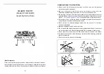
The casing / fi replace
• The casing may not be directly connected to the built-in fi re, but must be constructed
so that it is self-supporting; a mantle iron or lintel should be used for this. The
covering in the area must be of non-fl ammable materials of fl ame-retardant material
class A1. This includes bricks, cladding, ceramic tiles, metal or plasterwork, Promatec
and Nobranda.
• The opening for incoming and outgoing air from the casing must be at least totally
900 cm². At least 200 cm² from the opening for incoming and outgoing air must not be
closable.
• The ventilation of the casing/fi replace can be provided by grills, but this can also be
achieved by not building the fi replace right up to the ceiling (leaving a gap of 5 cm).
Содержание ENERGA 70-55 TUNNEL
Страница 2: ......
Страница 3: ...3 ENERGA 70 55 TUNNEL ENERGA 70 55 TUNNEL...
Страница 4: ...4 ENERGA 70 55 TUNNEL...
Страница 6: ...6 ENERGA 70 55 TUNNEL...
Страница 8: ...8 ENERGA 70 55 TUNNEL...
Страница 10: ...10 ENERGA 70 55 TUNNEL...
Страница 53: ...53 ENERGA 70 55 TUNNEL 13 DIMENSIONS 13 1 ENERGA 70 55 TUNNEL Combustion air supply connection 125 mm...
Страница 54: ...54 ENERGA 70 55 TUNNEL Combustion air supply connection 125 mm 13 1 1 ENERGA 70 55 Tunnel 3 sided 35 mm frame...
Страница 55: ...55 ENERGA 70 55 TUNNEL Combustion air supply connection 125 mm 13 1 2 ENERGA 70 55 Tunnel 4 sided 35 mm frame...
Страница 61: ......


