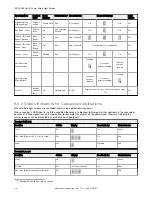

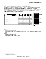
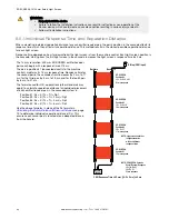
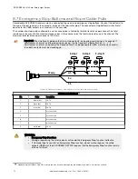


8.4 Determining Interconnect Cable Lengths
The following cable length charts are possible combinations for each side of example cascaded systems. All cables are
assumed to be 22 awg wire. Other lengths and combinations are possible; please call factory for assistance.
As the machine interface cable lengthens, the voltage drop increases, which results in shorter possible interconnect cables
to maintain supply voltage requirements at the cascaded sensor. See
on page 12 for a list of cordsets.
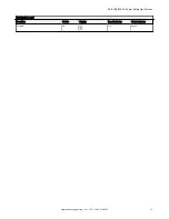
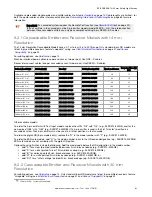
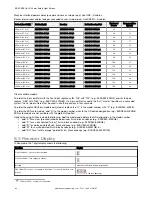
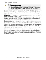
Table 4: Cable length options for two cascaded light screens
Recommended cable pairing per side of cascaded system
Machine Interface Cable (L1) QDE-..D
1 ft
3 ft
15 ft
25 ft
50 ft
Maximum L2 13
200 ft
200 ft
175 ft
135 ft
50 ft
Sensor
Interconnect
Cable Lengths
(L2)
Individual DEE2R-..D cables (ft)
100
100
100
100
75
75
75
75
50
50
50
50
50
25
25
25
25
25
15
15
15
15
15
3
3
3
3
3
1
1
1
1
1
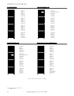
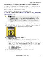
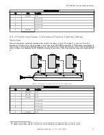
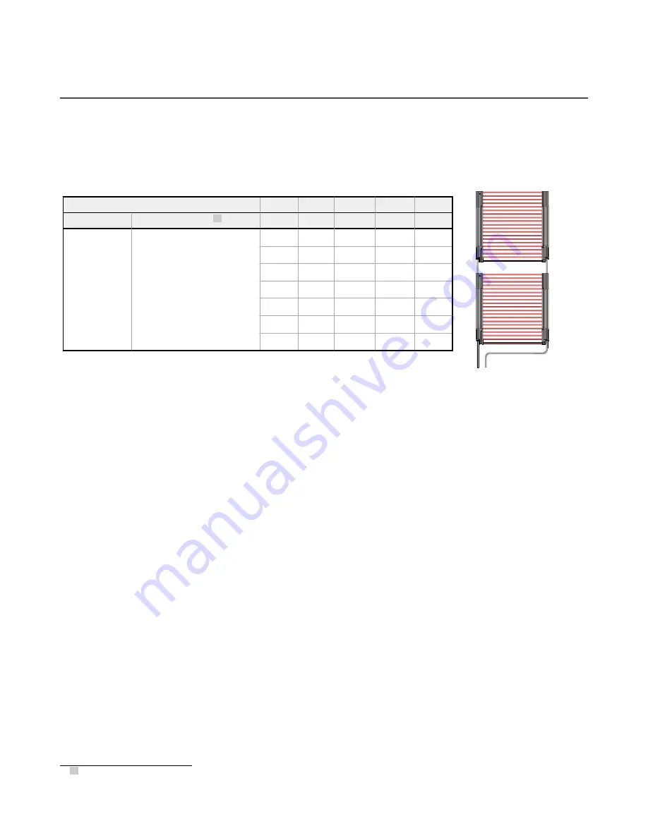
Emitters
Machine
Control
Receivers
L2
L1
EZ-SCREEN
Position #2
EZ-SCREEN
Position #1
Example 1:
Machine Interface Cable (L1): 15 ft
Sensor Interconnect Cable (L2): 175 ft (Using one 100 ft and one 75 ft DEE2R cables) or 100 ft or shorter using single
cables
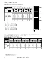
Example 2:
Machine Interface Cable (L1): 50 ft
Sensor Interconnect Cable (L2): 50 ft or shorter
13 Multiple DEE2R-..D cables may be required.
EZ-SCREEN
®
14/30 mm Safety Light Screen
www.bannerengineering.com - Tel: + 1 888 373 6767
65


