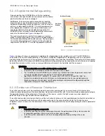
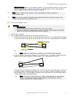
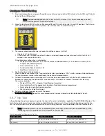
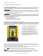
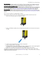
d. To optimize the alignment, note the position where the red Status indicator turns on when the sensor is
rotated both left and right. Center the sensor between the two positions, and tighten the end cap mounting
screws, making sure the positioning does not drift as the screws are tightened. Repeat for the second
sensor.
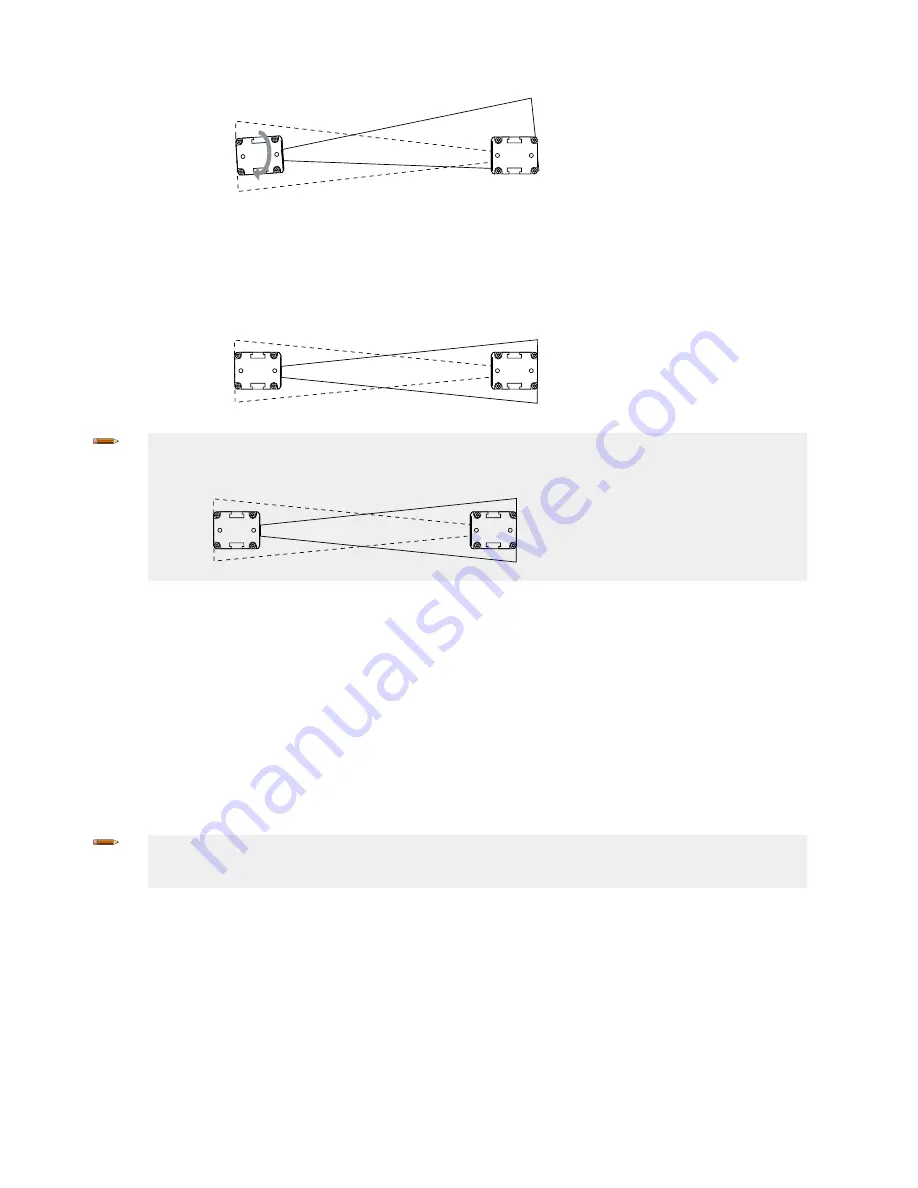
For situations where alignment is difficult, use a LAT-1-SS Laser Alignment Tool to assist or confirm
alignment by providing a visible red dot along the sensor’s optical axis.
Note: If at any time the red Status indicator begins to flash, the System has entered a Lockout condition.
See
on page 77 for more information.
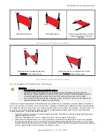
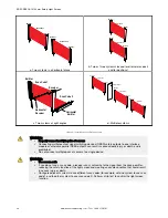
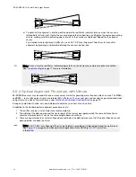
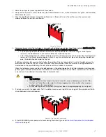
5.8.4 Optical Alignment Procedure with Mirrors
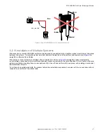
EZ-SCREEN sensors may be used with one or more corner mirrors for guarding more than one side of an area. The MSM-...
and SSM-... rear-surface glass mirrors are rated at 85% efficiency. Thus, excess gain and sensing range are reduced when
using mirrors; see Use of Corner Mirrors, under
Mechanical Installation Considerations
on page 19.
During any adjustments, allow only one individual to adjust any one item at any one time.
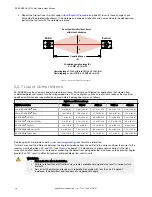
In addition to the standard optical alignment procedure, verify:
1. The emitter, receiver, and all mirrors are level and plumb.
2. The middle of the defined area and the center point of the mirrors are approximately the same distance from a
common reference point, such as the same height above a level floor.
3. There are equal amounts of mirror surface above and below the defined area such that the optical beams are not
passing below or above the mirror.
Note: A LAT-1-SS Laser Alignment Tool is very helpful by providing a visible red dot along the optical axis.
on page 35 and Banner Safety Applications Note SA104 (p/n
) for further
information.
EZ-SCREEN
®
14/30 mm Safety Light Screen
34
www.bannerengineering.com - Tel: + 1 888 373 6767


