background image

ENGLISH

Vulcan Series

Installation Manual

bandg.com

Содержание Vulcan Series

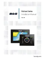
Страница 1: ...ENGLISH VulcanSeries Installation Manual bandg com...

Страница 2: ......

Страница 3: ...on manuals user guides and other information relating to the product Documentation may be translated to or has been translated from another language Translation In the event of any conflict between an...

Страница 4: ...undesired operation of the device Le pr sent appareil est conforme aux CNR d Industrie Canada applicables aux appareils radio exempts de licence L exploitation est autoris e aux deux conditions suivan...

Страница 5: ...rom that of the receiver Consult the dealer or an experienced technician for help Countries of intended use in the EU AT Austria BE Belgium BG Bulgaria CY Cyprus CZ Czech Republic DK Denmark EE Estoni...

Страница 6: ...Electronics Ltd C MAP is a trademark of Jeppesen The terms HDMI and HDMI High Definition Multimedia Interface and the HDMI Logo are trademarks or registered trademarks of HDMI Licensing LLC in the Un...

Страница 7: ...xt that requires special attention from the reader is emphasized as follows Note Used to draw the reader s attention to a comment or some important information Warning Used when it is necessary to war...

Страница 8: ...8 Preface Vulcan Series Installation Manual...

Страница 9: ...idelines 22 Power Connections 23 Power Control connection 24 External alarm 25 Connecting control devices 25 NMEA 2000 backbone 27 CZone connection to NMEA 2000 28 Transducer connection 29 Software Se...

Страница 10: ...A 2000 compliant PGN List 61 Specifications 61 Mechanical Environmental 61 Electrical 62 Interfaces 63 Dimensional drawings 63 Vulcan 5 Dimensional drawings 63 Vulcan 7 FS Dimensional drawings 10 Cont...

Страница 11: ...LIS H InstallationManual bandg com 1 2 4 5 6 7 10 9 11 8 3 1 Vulcan 5 2 Sun cover 3 Panel mount gasket 4 Cap 2x on NMEA 2000 and Sonar connectors 5 Fuse holder ATC blade 6 Fuse 3 amp 7 Power NMEA 2000...

Страница 12: ...dg com 1 2 4 5 6 7 10 9 12 11 8 3 1 Vulcan 7 FS 2 Sun cover 3 Panel mount gasket 4 Caps 2x on NMEA 2000 and Sonar connectors 5 Fuse holder ATC blade 6 Fuse 3 amp 7 Power cable 8 Panel mount screws 4x...

Страница 13: ...y a variety of third party mapping providers in the AT5 format For a full selection of available charts visit gofreeshop com c map jeppesen com or navionics com The unit may be mounted to the vessel w...

Страница 14: ...5 rear connections SONAR PWR N2K 1 2 3 1 Sonar CHIRP Broadband DownScan and SideScan imaging dependent on the transducer 2 Card reader 3 Power 12 V DC supply input and NMEA 2000 14 Overview Vulcan Ser...

Страница 15: ...NMEA2000 POWER SONAR 1 2 3 4 1 NMEA 2000 data input output 2 Power 12 V DC supply input 3 Sonar CHIRP Broadband DownScan and SideScan imaging dependent on the transducer 4 Card reader Overview Vulcan...

Страница 16: ...of user data and system backup The card reader door is opened by pulling the rubber cover open The card reader door should always be securely shut immediately after inserting or removing a card in ord...

Страница 17: ...cables to the intended mounting location Leave sufficient clearance to connect all relevant cables Do not mount any part where it can be used as a hand hold where it might be submerged or where it wi...

Страница 18: ...sen location has enough height to accommodate the unit fitted in the bracket allows tilting of the unit and connecting cables in the back Note Ensure that the chosen location has enough height to acco...

Страница 19: ...le Removing the unit from the quick release bracket Pull and hold the release handle and then pull the unit from the bracket U Bracket mounting The Vulcan 7 FS can be mounted with the U bracket Instal...

Страница 20: ...it or mount the bracket with machine screws and large washers Use only 304 or 316 stainless steel fasteners 3 Screw down the bracket 4 Mount the unit to the bracket using the knobs Hand tighten only...

Страница 21: ...MEA 2000 cables Do leave room adjacent to connectors to ease plugging and unplugging of cables Warning Before starting the installation be sure to turn electrical power off If power is left on or turn...

Страница 22: ...he following Power into the system Red and Black wires Controlling power state of the unit Yellow wire 1 6 _ 2 3 5 4 1 Power cable 2 12 V DC positive wire red shown with fuse holder fitted 3 12 V DC n...

Страница 23: ...lue wire _ 1 2 3 5 6 4 1 Power cable 2 12 V positive wire red shown with fuse holder fitted 3 12 V negative wire black 4 Power control wire yellow 5 Alarm wire blue 6 Vessel s 12 V DC supply Connect R...

Страница 24: ...the yellow wire to the accessories output of the engine key switch Note Engine start batteries and house batteries should have a common ground connection External alarm Note An external alarm can be...

Страница 25: ...connection The unit is equipped with an NMEA 2000 data port which allows the receiving and sharing of a multitude of data from various sources Planning and installing a network backbone The backbone n...

Страница 26: ...dapter cables Power the network The network requires its own 12 V DC power supply protected by a 3 amp fuse or breaker Connect power at any location in the backbone for smaller systems For larger syst...

Страница 27: ...he CZone NMEA 2000 Network interface bridge isolates the power of the two networks but allows data to be freely shared between both sides The Interface Bridge can also be used for expansion of the NME...

Страница 28: ...the unit For connector location refer to the embossed labeling on the back of the unit Note The connector attached to the transducer cable is keyed and can only be inserted in one orientation Once ins...

Страница 29: ...system settings option and later change settings made with the setup wizard Time and Date Configure time settings to suit vessel location along with time and date formats Data source selection Data so...

Страница 30: ...ple position wind direction and so on that all other products on the network use or alternatively use a data source independently from other units Globally change all displays over to a different sour...

Страница 31: ...of the Sources list and under each source category for example Compass The latter shows a filtered list that only relates to devices that output data relevant to the category Sonar setup The Installa...

Страница 32: ...is used for selecting the transducer model connected to the sonar module The transducer selected will determine what frequencies the user can select during sonar operation In some transducers with bu...

Страница 33: ...hysical STBY key is required for commissioning This can be on the autopilot control head or on an autopilot remote controller When the autopilot installation is completed the commissioning procedures...

Страница 34: ...p through the process 1 Press the STBY key to ensure that the autopilot is in standby mode 2 Select the Commissioning option and clear the displayed dialog by pressing the STDBY key 3 Select your boat...

Страница 35: ...cribed in the on screen instructions Note If the boat uses power assisted steering it is important that the engine or electric motor used to enable the power assist steering is turned on prior to this...

Страница 36: ...ction circuits are activated Drive engage Clutch This is the default setting and it allows you to steer the boat with the helm or wheel when in STBY mode FU and NFU modes as well as in all auto steeri...

Страница 37: ...time during the seatrial by pressing the STBY key on the ZC1 The following seatrial calibration should be done Compass calibration used to automatically compensate for on board magnetic interference...

Страница 38: ...o be accepted Compass mounting offset After compass calibration the difference if any between the compass lubber line and the boat s center line should be compensated for 1 Find the bearing from the b...

Страница 39: ...are used HI A High response parameters set automatically LO A Low response parameters set automatically HI M High response parameters set manually LO M Low response parameter set manually Autotuning T...

Страница 40: ...y It may be used to manually find the optimum combination of course keeping and low rudder activity in rough but steady sea conditions Setting sailing parameters Note Sailing parameter settings are on...

Страница 41: ...topilot when heading downwind or close to while steering to apparent wind is used when beating or reaching Apparent wind steering is preferred when you want to maintain maximum boat speed without cont...

Страница 42: ...ng will be unstable Counter rudder Counter rudder is the amount of rudder used to try to prevent the boat from yawing around the set course Higher counter rudder settings result in more rudder being a...

Страница 43: ...me boats However this will increase the rudder activity Minimum wind angle to port and starboard These parameters should be set identical to the minimum apparent wind angle that will keep the sails fr...

Страница 44: ...ensor nor the Suzuki engine interface require the use of a separate Fuel Storage device Refer to the engine manufacturer or dealer for information on whether or not your engine provides a data output...

Страница 45: ...estores only the Fuel K Value setting if set in Calibrate Only Navico devices can be reset Calibrate Calibration may be required to accurately match measured flow with actual fuel flow Access calibrat...

Страница 46: ...all engines Note The Calibrate option is only available when Set to full is selected and a Fuel Flow is connected and set up as a source Note A maximum of 8 engines is supported using Fuel Flow senso...

Страница 47: ...is determined by the CZone Config File zcf which is stored on all CZone modules and the Vulcan The file is created using the CZone Configuration Tool a specialized PC application available from BEP M...

Страница 48: ...set as a controller Import and backup a configuration file The files page may be used to import CZone configuration files or export a copy to a memory card in the card reader Importing overwrites the...

Страница 49: ...tions to manually find the device 5 Select the graphic icon of the unit The unit displays a prompt similar to the following 6 Select Yes for one time connection or Always if device is to be remembered...

Страница 50: ...he vessel so weak spots or problem areas can be identified The application must be installed on and run from a tablet device The Vulcan must be running Iperf server before initiating the test from the...

Страница 51: ...ide support related to their use Internal Wireless Select this option to enable or disable the internal wireless module Disabling wireless when not in use reduces the unit s power consumption NMEA 200...

Страница 52: ...Zone configuration files Insert a memory card into the unit s card reader as a storage location for backup data Waypoints Routes and Tracks database backup You can export all Waypoints Routes and Trac...

Страница 53: ...e root directory of the memory card The update may be initiated at boot up insert the memory card into the card reader before turning the unit on boot the unit and follow the on screen instructions Al...

Страница 54: ...tion presented when the file is highlighted A list should appear displaying any compatible devices the update file applies to In most cases this will be a single device Note If no device is shown chec...

Страница 55: ...ezel 000 13169 001 Panel Mount Kit 000 12572 001 7 pin Transducer to 9 pin Adapter Cable Vulcan 7 FS Accessories Part number Description 000 12366 001 Flush Mount Kit 000 12368 001 Flush Mount Sun Cov...

Страница 56: ...2000 Configuration 65323 Data User Group Request 65325 Reprogram Status 65341 Autopilot Mode 65480 Autopilot Mode 126208 ISO Command Group Function 126992 System Time 126996 Product Info 127237 Headin...

Страница 57: ...S Class B Extended Position Report 129041 AIS aids to Navigation 129283 Cross Track Error 129284 Navigation Data 129539 GNSS DOPs 129540 AIS Class B Extended Position Report 129794 AIS aids to Navigat...

Страница 58: ...Reply 130817 Product Info 130820 Reprogram Status 130831 Suzuki Engine and Storage Device Config 130832 Fuel Used High Resolution 130834 Engine and Tank Configuration 130835 Set Engine And Tank Confi...

Страница 59: ...oduct Info 127237 Heading Track Control 127250 Vessel Heading 127258 Magnetic Variation 128259 Speed Water referenced 128267 Water Depth 128275 Distance Log 129025 Position Rapid Update 129026 COG SOG...

Страница 60: ...ine and Storage Device Config 130835 Set Engine And Tank Configuration 130836 Fluid Level Insect Configuration 130837 Fuel Flow Turbine Configuration 130839 Pressure Insect Configuration 130845 Weathe...

Страница 61: ...ightness 1200 nits Screen resolution 480 x 800 H x W Viewing angle in degrees typical value at contrast ratio 10 L R 70 top 50 bottom 60 Dimensions overall See dimension drawings Electrical Operating...

Страница 62: ...nt 1 port Micro C male Vulcan 7 FS only network load 1 LEN 1 combined port Power and NMEA 2000 7 pin connector Vulcan 5 only Sonar 1 port 9 pin connector Card reader 1x microSD 62 Specifications Vulca...

Страница 63: ...4 0 mm 3 70 136 0 mm 5 35 120 mm 4 72 94 0 mm 3 70 117 5 mm 4 62 58 0 mm 2 28 Vulcan 7 FS Dimensional drawings 199 0 mm 7 84 65 0 mm 2 60 28 5 mm 1 12 37 0 mm 1 45 220 00 mm 8 66 154 0 mm 6 06 142 0 m...

Страница 64: ...988 11099 001 0980...

Отзывы:

Похожие инструкции для Vulcan Series