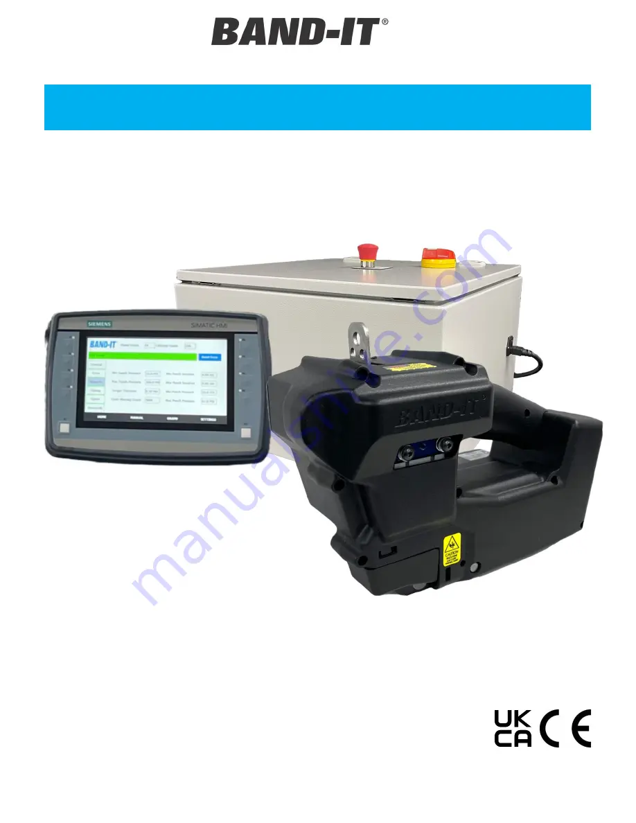
Band-it IT7000 Скачать руководство пользователя страница 1


User Manual 

IT8000 3/8” TIE

-LOK DATA TOOL 

IT7000 1/4” TIE

-LOK DATA TOOL 

ITC800 CONTROL SYSTEM 

Document # P80080 Rev. C.3 

© Copyright 

BAND-IT-IDEX, Inc. 2024 

All rights reserved 


All rights reserved 

BAND-IT-IDEX, Inc. 
A Unit of IDEX Corporation 
4799 Dahlia Street 
Denver, CO 80216-3070 USA 
P: 1-800-525-0758 


IT8000/IT7000/ITC800


User Manual 


Original Instructions 
(Not a translation) 

Содержание IT7000

Страница 1: ...C800 CONTROL SYSTEM Document P80080 Rev C 3 Copyright BAND IT IDEX Inc 2024 All rights reserved BAND IT IDEX Inc A Unit of IDEX Corporation 4799 Dahlia Street Denver CO 80216 3070 USA P 1 800 525 0758...

Страница 2: ...ERVIEW 8 QUICK START OVERVIEW 8 ENVIRONMENT 9 TRANSPORTATION STORAGE HANDLING 9 TOOL SETUP 10 OPERATING REQUIREMENTS 10 PART DESCRIPTIONS AND LOCATIONS 11 INSTALLATION TOOL DIMENSIONS IT8000 13 INSTAL...

Страница 3: ...et Denver CO 80216 3070 USA P 1 800 525 0758 HARNESS ROUTING 29 TOOL CLEARANCE REQUIREMENTS 30 SENSOR ACTIVATION 31 REMOTE ACTUATION 31 CUT OFF SIGNAL 31 FACTORY PROGRAM SETTINGS 32 SOFTWARE AND ELECT...

Страница 4: ...provided in this document o Never use this product for anything other than its original intended purpose IMPORTANT o The object clamped and the 3 8 Tie Lok tie or 1 4 Tie Lok tie must be compatible w...

Страница 5: ...tention to all danger and caution statements Failure to do so could result in serious injury to the operator or other personnel or damage to the equipment SAFETY SIGNS High Voltage Risk of electric sh...

Страница 6: ...in enclosure Power cord Main method of removing power to unit Unplug from wall or main enclosure Interlocking functions and features The tool is not intended to operate without guards in place The too...

Страница 7: ...eserved BAND IT IDEX Inc A Unit of IDEX Corporation 4799 Dahlia Street Denver CO 80216 3070 USA P 1 800 525 0758 PRODUCT SAFETY LOCATIONS Warning Do not place fingers hands or any body parts under the...

Страница 8: ...he finished assembly QUICK START OVERVIEW 1 Connect data and motor cable to tool Page 16 Note Ensure controller power and air are off before connecting to the tool Page 16 2 Connect data cable to cont...

Страница 9: ...automotive assembly plant or similar facility Temperature range from 5 C to 40 C 41 F to 95 F Max relative humidity 80 for temperatures up to 31 C 88 F decreasing linearly to 50 at 40 C 104 F Conform...

Страница 10: ...n Do not exceed 100psi 690kPa into panel Input supply not to exceed max listed on regulator assembly Power requirements 110Volts 60Hz or 240Volts 50Hz Grounded AC 8 A Max 5kA SCCR Power Cord North Ame...

Страница 11: ...reet Denver CO 80216 3070 USA P 1 800 525 0758 PART DESCRIPTIONS AND LOCATIONS Clamp Cylinder Pinch Arm Upper Band Guide Lower Band Guide Backing Wheel Punch Punch Holder Trigger Link Tension Wheel Pu...

Страница 12: ...SYSTEM Document P80080 Rev C 3 Copyright BAND IT IDEX Inc 2024 All rights reserved BAND IT IDEX Inc A Unit of IDEX Corporation 4799 Dahlia Street Denver CO 80216 3070 USA P 1 800 525 0758 PART DESCRIP...

Страница 13: ...TA TOOL ITC800 CONTROL SYSTEM Document P80080 Rev C 3 Copyright BAND IT IDEX Inc 2024 All rights reserved BAND IT IDEX Inc A Unit of IDEX Corporation 4799 Dahlia Street Denver CO 80216 3070 USA P 1 80...

Страница 14: ...TA TOOL ITC800 CONTROL SYSTEM Document P80080 Rev C 3 Copyright BAND IT IDEX Inc 2024 All rights reserved BAND IT IDEX Inc A Unit of IDEX Corporation 4799 Dahlia Street Denver CO 80216 3070 USA P 1 80...

Страница 15: ...080 Rev C 3 Copyright BAND IT IDEX Inc 2024 All rights reserved BAND IT IDEX Inc A Unit of IDEX Corporation 4799 Dahlia Street Denver CO 80216 3070 USA P 1 800 525 0758 CONTROLLER ENCLOSURE DIMENSIONS...

Страница 16: ...or the key is misaligned Connect the motor cable to the motor Ensure the connector is fully rotated in the direction of the open arrow align the two triangles on the cable and motor push cable onto mo...

Страница 17: ...r tool data The system regulator has two connections that must be connected Fig 19 Each electrical connector has a unique interface do not attempt to force a plug into a connector if the receptable do...

Страница 18: ...xtend line Fig 21 The punch must be extended to read the pressure The punch pressure reading is shown on the manual screen pg 35 The regulators are adjusted independently Note that the HMI pressure li...

Страница 19: ...scrap Otherwise the tool will wait for the next trigger press to eject scrap Note Regardless of the setting the scrap will have to be pulled out by hand See HMI settings to change the setting pg 37 Ev...

Страница 20: ...ntroller back on Ensure Door Latch is in the On position 7 Tool Setup automatically appears skip step 1 if not go to settings screen General tab 1 Select New Tool Maintenance 2 Select the Enter Serial...

Страница 21: ...tensioning and open the gripper 7 The tool will continue to run until it reaches the desired tension At this point the tool will hold tension but not fire the punch until the tool is moved tangent to...

Страница 22: ...over air gaps Fig 32 Avoid sharp corners add largest radius possible on square corners Fig 31 Tie Lok can be installed on flat surfaces Do not install clamps on tapered surfaces or on tube bends Fig...

Страница 23: ...assistance arm Tool Balancer The tool needs to be located directly above the clamp location if using a balancer as shown below Figures 34 35 The balancer must support the weight of approximately 10 lb...

Страница 24: ...lled with the same tool a slide rail or swing arm is required to move between the ties Always allow the tool to hang directly above the installation Pulling the tool at an angle will cause increased s...

Страница 25: ...ommended Setup For the most ergonimic design we recommend moutning the tool on an articulating arm or fixture Articulating Arms Three 10 32 mounting holes are provided to attach the IT8000 IT7000 to a...

Страница 26: ...ckle is installed tangent to the work piece A minimum of 30 of rotation is required for the tool to operate but 120 is recommended The tool should be allowed to rotate both forwards and backwards from...

Страница 27: ...t Denver CO 80216 3070 USA P 1 800 525 0758 Figure 45 Figure 46 Figure 47 CENTER OF GRAVITY The center of gravity CG is shown below in relation to the hanger loop and mounting holes The closer the rot...

Страница 28: ...DEX Inc A Unit of IDEX Corporation 4799 Dahlia Street Denver CO 80216 3070 USA P 1 800 525 0758 Figure 48 Figure 51 Figure 50 Figure 49 MOUNTING EXAMPLES Figures 48 51 are an example of an articulatin...

Страница 29: ...an be used Figure 53 Note that the center of gravity is behind the hanger bracket For best performance the pivot point should be located on the CG not directly on the hanger bracket HARNESS ROUTING It...

Страница 30: ...nc A Unit of IDEX Corporation 4799 Dahlia Street Denver CO 80216 3070 USA P 1 800 525 0758 TOOL CLEARANCE REQUIREMENTS Minimum Clearance Requirements Dimension Description IT8000 in mm IT7000 in mm A...

Страница 31: ...ed on an assembly The connector is located next to the remote actuation on the controller If using the Mencom yellow cable measure the signal across the white and blue wires Contact BAND IT IDEX for r...

Страница 32: ...General Target Torque 40 30 Setpoints Min Supply Pressure 75 PSI Max Supply Pressure 85 PSI Torque Tolerance 0 10 in lbf Min Punch Duration 0 5 ms Max Punch Duration 5 0 ms Min Punch Pressure 63 PSI...

Страница 33: ...rporation 4799 Dahlia Street Denver CO 80216 3070 USA P 1 800 525 0758 SOFTWARE AND ELECTRONICS HMI OVERVIEW Device Start Up When the tool is first powered on the previous screen will appear for 20 se...

Страница 34: ...ut regulator controls the non punch cylinders Punch Pressure Pressure reading inside tool controls only the punch cylinder Motor Torque Instantaneous motor torque Punch Max Duration Max duration for t...

Страница 35: ...anual screen The tool will not install a clamp in this state An LED on the F1 button will blink to alert you that the tool is still in manual mode Pull Band Rotates the motor to pull the tie into the...

Страница 36: ...o has two vertical lines where the Punch and Cut happen All data shown on the graph screen is stored in the PLC When switching to the graph screen the HMI will auto populate with the most recent cycle...

Страница 37: ...typically a full days worth of installs Maintenance History File format is Maintenance_History Copy Log to USB transfers the selected file to USB flash drive if installed If a duplicate file name is a...

Страница 38: ...hitting Reset Error Enable Error Codes Passcode Requires a passcode to clear an error Error Codes to Require Passcode Number of errors in a row before the passcode is needed Settings Screen Setpoints...

Страница 39: ...nsors are activated Position Sensors Debounce How long the proximity sensors need to be in position before the tool completes the cycle Cut off delay Delay between punch and cut Punch Extend Duration...

Страница 40: ...d to Reset Error Optional Settings Administrator Password Password required to access the SETTINGS tab Password screen will pop up if Log In is attempted on the HOME screen Auto logout is available fo...

Страница 41: ...Window When you select the Service button in the top right of the screen the Maintenance Interval window pops up If the Current Cycles count is greater than the Reccomended Cycles count for any of th...

Страница 42: ...has not been changed select Tool Not Replaced If the tool has been replaced enter the tool serial number select which maintenance items have been executed a white X appears in the left column select Y...

Страница 43: ...eaner into the pneumatic system Do not remove factory applied lubrication from inside tool unless performing a thorough maintenance procedure and then replacing with clean lubricant immediately Follow...

Страница 44: ...backing wheel pin through the grease port on side of tool Lincoln 5803 or similar needle type grease fitting is required Lubricating the knife requires partially sliding it out see page 46 for instru...

Страница 45: ...wing down Be careful to ensure the backing wheel and pin do not slide out with the pinch arms removed 2 Enter manual mode to drive the tension wheel for a few revolutions with the wire brush 1 4 brush...

Страница 46: ...o remove Remove the E Clips 2 on the non motor side only Push the 2 pins 3 down far enough to allow the linkage 4 to swing out Remove the knife 5 Apply a film of grease to the new knife and pins and r...

Страница 47: ...connect the sensor cable and remove the head 6 Apply a film of grease on the pins and knife and reassemble Ensure that the upper pin goes through the trigger assembly linkage 7 Fig 81 Apply Blue Locti...

Страница 48: ...ure 82 PUNCH REPLACEMENT Remove the head as shown on page 47 Extend the cylinder by pulling on the punch 1 until the punch holder is visible Punch the spring pin 3 32 Dia 2 out Reassemble Always using...

Страница 49: ...3 and drop the pinch arms 4 Remove retaining ring 5 Remove ball bearing 6 Remove gripper wheel 7 A small pry bar may be required to break the gripper free from the gearbox shaft This will also break t...

Страница 50: ...between motor and gearbox is tight Check for foreign object present or other obstructions Pre set tension is not reached Tension Wheel slipping Inspect clamp tail for evidence of slipping Clean Tensi...

Страница 51: ...ubing and fittings for obstructions Clamp buckle located above void or opening Be sure to locate buckle on fully supported surface Object being clamped is hand held Small light weight objects clamped...

Страница 52: ...bserve keyed orientation of the connectors All threaded sleeves on connectors must be fully assembled and secured Power entry plug switch or door latch turned Off Check switch status Internal Circuit...

Страница 53: ...not stop the sequence and the tool can complete an installation when these occur but they may mean that the tool has not installed the band to the right specifications Error messages will persist when...

Страница 54: ...uction in punch assembly damaged punch cylinder 213 Parameters Not Passed Torque Out of Tolerance This error will occur after a completed cycle if the measured motor torque is outside of the allowed r...

Отзывы: