32
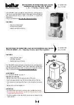
INSTRUCTIONS FOR VALVES EQUIPPED WITH
PRESSURE REGULATOR mod. SKP 20....
N° 8882-GB
rev. 06/11/90
DESCRIPTION OF HOW THE VALVE OPERATES
Servomotor
The hydraulic control system consist of a cylinder filled with oil and oscillating piston pump. There is also a
solenoid valve between the intake chamber and the pump thrust chamber, to close the valve. The piston moves
against a sealed joint inserted into the cylinder; in turn, this joint hydraulically separates the intake chamber from
the delivery chamber. The piston transmits the stroke directly to the valve. A disk is secured to the valve shaft
and can be seen through a slit in the valve, indicating the stroke.
PRESSURE REGULATOR
The pressure regulator consists of a diaphragm (there is also an additional safety diaphragm), a spring calibrated
to a setpoint and an oscillating system to drive the ball valve located on the bypass between the hydualic system
intake and delivery chambers (also see “Description of how the valve works”).
Operating range: 0...22 mbar or (subject to replacement of the spring) up to 250 mbar.
Regulation to the set value can be sealed. Gas pressure inlet connection starting at
1
/
4
”.
Thanks to the use of a safety diaphragm, no gas vent piping is required for inlet pressure up to 100 mbar. Under
tightness testing, it can tollerate a vacuum pressure of up to 200 mbar.
The casing of the servomotor and the pressure regulator are in cast aluminum.
DESCRIPTION OF HOW GAS VALVES FITTED WITH PRESSURE REGULATOR OPERATE
When a valve fitted with a pressure regulator is used, the valve outlet pressure presses against a spring-assisted
diaphragm, acting as a reference value. The force of this spring can be adjusted and is set at the prescribed
value. The diaphragm, activated by an oscillating piston system, presses against the ball bypass valve located
between the lower and upper chambers of the servocontrol unit. If the reference value is lower than the setpoint,
the bypass is closed so that the servocontrol can open the gas valve. On the contrary, if the reference value is
higher than the setpoint, the bypass is open a degree enabling oil to return to the lower chamber.
The gas valve closes gradually until setpoint coincides with the gas reference pressure value. When this well-
balanced position is reached, the bypass is open so that flow rate corresponds to pump flow rate.
In this way, the regulator operates as a proportional regulator over a very narrow range. Nevertheless, regulation
remains stable because the speed at which the valve closes is reduced.
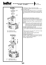
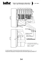
Remove screw cap cover “C” to access the
pressure regulation screw “A”.
Tighten to increase the pressure, loosen to
decrease the pressure.
Screw “D” in terminal “IV” regulates the position
at which the “clean” contact is activated.
This can be used for an outside signal.
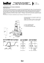
D = Driver identification plate
E = Flow direction indicator
F = Valve body identification plate
B
type
Po
colour
(mm)
(mbar)
1,0
--
< 22
bright
1,6
AGA22
< 120
yellov
1,6
AGA 23
< 250
red
Содержание TS 0 GN
Страница 2: ......
Страница 47: ......
Страница 48: ......
Страница 49: ......
Страница 50: ......
Страница 51: ......
Страница 52: ......
Страница 53: ......
Страница 54: ......
Страница 55: ......
Страница 56: ......
Страница 57: ......
Страница 58: ......
Страница 59: ......
Страница 60: ......
Страница 61: ......
Страница 62: ......
Страница 63: ......
Страница 64: ......
Страница 65: ......
Страница 66: ......
Страница 67: ......
Страница 68: ......
Страница 69: ......
Страница 70: ......
Страница 71: ......
Страница 72: ......
Страница 73: ......
Страница 74: ......
Страница 75: ......
Страница 76: ......
Страница 77: ......
Страница 78: ......
Страница 79: ......
Страница 80: ......
Страница 81: ......
Страница 82: ......
Страница 83: ......
Страница 84: ......
Страница 85: ......
Страница 86: ......
Страница 87: ......
Страница 88: ......
Страница 89: ......
Страница 90: ......
Страница 91: ......
Страница 92: ......
Страница 93: ......
Страница 94: ......
Страница 95: ......

