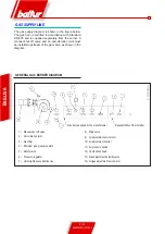
11 / 20
0006081531_201203
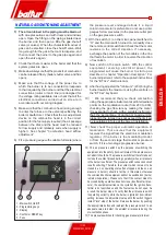
dis
pla
y l
am
te
c B
T3
xx
3
4
1
2
5
ENGLISH
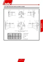
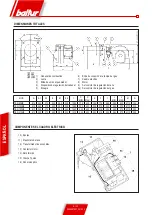
1 - Main switch On/Off
2 - Programming keys
3 - Display
4 - Confirm or RESET key
5 - Fuse
NATURAL GAS IGNITION AND ADJUSTMENT
1) The air contained in the piping must be bled out
,
with due precautions and with doors and windows
open. Open the fitting on the piping situated near
the burner and then open a little the gas shut-off
valve (or valves). When the characteristic odour of
gas can be smelled, close the shut-off valve. Wait
long enough for the gas in the room to disperse, and
then connect the burner to the gas pipe again and
open the valve again.
2) Check that there is water in the boiler and that the
system gates are open.
3) Make absolutely sure that the products of combustion
can be released freely (boiler shutter valve and flue
open).
4) Make sure that the voltage of the power line to
which the burner is to be connected corresponds
to that required by the burner and that the electrical
connections (motor or main line) are designed for
the voltage rating available. Also check that all the
electrical connections carried out on site are in
accordance with our wiring diagram.
5) Make sure that the combustion head is long enough
to enter the furnace to the extent specified by the
boiler manufacturer. Check that the air adjustment
device on the combustion head is in the correct
position for the fuel supply required (the air passage
between the disk and the head must be reduced
for low supply and relatively wide when supply is
higher). See chapter “Combustion head airflow
adjustment”.
6) Fit a pressure gauge with suitable full scale (where
the pressure level envisaged allows it, a liquid
column manometer is preferable; do not use pointer
gauges for low pressures) to the pressure outlet port
on the gas pressure switch.
7) With the switch (1) on the mimic panel switched to
“O” and the main switch turned on, manually close
the remote control switch and check that the motor
revolves in the correct direction. If necessary,
exchange the position of the two cables in the line
that feeds the motor in order to reverse the direction
of revolution.
8) Now switch on the main switch. With the control
equipment receiving electrical power, the
programmer will cause the burner to start up as
described in chapter “Operation description”. For
burner adjustment, refer to the supplied instructions
for the "BT 3xx" electronic cam.
9) After having adjusted the "minimum", (200) bring the
burner towards the maximum, using the controls on
the “BT 3xx” keyboard.
10)
We recommend that you check combustion
using the appropriate instrument at all intermediate
points on the modulation route (from 200 to 999),
checking the gas flow rate by reading the meter.
It is essential to check, with a suitable instrument,
that the percentage of carbon monoxide (CO)
present in the fumes does not exceed the limit set
by regulations in force at the time of installation.
11) Now check the proper automatic operation of
modulation. This ensures that the equipment
receives the signal from the electronic modulation
regulator, if the burner is the modulating model,
or from the second stage thermostat or pressure
switch, if it is a two stage progressive burner.
12) The air pressure switch has the purpose of switching the
equipment into the safety (lock-out) status if the air pressure is
not what it should be. The pressure switch must therefore be set
to close the contact (closed during operation) when air pressure
in the burner is sufficient. The pressure switch connection circuit
is self controlling. Therefore, the contact which is meant to be
closed in a non operating status (fan stopped and thus no air
pressure in burner), should in fact be in this status, otherwise
the command/control equipment will not be switched on (burner
remains inoperative). Please note that if the contact meant to
be closed during operation does not close (insufficient air pres-
sure), the equipment carries out its cycle but the ignition trans-
former is not switched on and the fuel valves do not open. As
a result, the burner stops. To verify that the air pressure switch
is operating correctly, while the burner is ignited at its minimum
setting, increase the adjustment value until the switch triggers
instant “lock” stop of the burner. Release the burner by pushing
the appropriate button and readjust the pressure switch to an
adequate value to detect the existent air pressure during the
pre-ventilation phase.
13) The pressure switches for checking gas pressure (minimum
Содержание TBG 85 ME
Страница 2: ......
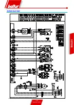
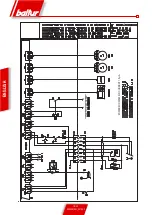
Страница 19: ...17 20 0006081531_201203 ENGLISH WIRING DIAGRAM...
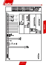
Страница 20: ...18 20 0006081531_201203 ENGLISH START FOR RECORDER MINIMUM IONISATION CURRENT 1 5 A...
Страница 39: ...17 20 0006081531_201203 ESPA OL ESQUEMA EL CTRICO...
Страница 40: ...18 20 0006081531_201203 ESPA OL ARRANQUE PARA REGISTRADOR CORRENTE M NIMA DE IONIZACI N 1 5 A...
Страница 59: ...17 20 0006081531_201203 FRAN AIS SCHEMA ELECTRIQUE...
Страница 60: ...18 20 0006081531_201203 FRAN AIS MARCHE POUR ENREGISTREUR COURANT D IONISATION MINIMUM 1 5 A...
Страница 79: ...17 20 0006081531_201203 T RK E ELEKTR K EMASI...
Страница 80: ...18 20 0006081531_201203 T RK E REG LAT R N BA LATMA M N MUM YON ZASYON AKIMI 1 5 A...
Страница 84: ...2 20 0006081531_201203 PYCCK BALTUR a b c a b c d e f g...
Страница 85: ...3 20 0006081531_201203 PYCCK 2 RC a b c d e a b a b c d...
Страница 89: ...7 20 0006081531_201203 PYCCK A 5 6 B 3 2 C 4 1 7 8 8a 9 DN65 DN80 A B 10 C 11...
Страница 90: ...8 20 0006081531_201203 N 0002910950n2 PYCCK EN676 1 2 3 4 5 6 7 8 9 10 11 12 13 14...
Страница 92: ...10 20 0006081531_201203 A B farfallaTBG ME PYCCK 3 RESET 4 B LAMTEC BT 3xx BT 3xx 30 2 200 999 BT 3xx...
Страница 94: ...12 20 0006081531_201203 ioniz_BT3xx PYCCK 1 4 A 13 14 15...
Страница 97: ...15 20 0006081531_201203 figura 1 figura 2 figura 4 figura 3 PYCCK 2 1 3 4 5 8 6 8 9 0002934691 7 2...
Страница 99: ...17 20 0006081531_201203 PYCCK...
Страница 100: ...18 20 0006081531_201203 PYCCK 1 5 A...
Страница 101: ...19 20 0006081531_201203 PYCCK 0 4 20 A...
Страница 104: ...2 20 0006081531_201203 a b c a b c d e f g I...
Страница 105: ...3 20 0006081531_201203 2 RC a b c d e a b a b c d I...
Страница 109: ...7 20 0006081531_201203 5 6 2 3 7 4 1 8 8A 9 DN65 DN80 10 11...
Страница 110: ...8 20 0006081531_201203 N 0002910950n2 EN676 1 2 3 4 5 6 7 8 9 10 11 12 13 14...
Страница 111: ...9 20 0006081531_201203 1 4 1 2 3 7 2 4 5 3 6 7 9 5 10 mm 8 5 9mm IP 54 CEI EN60529 5Nm 4 1 8 4 7 5 9 2 3 4 5 1...
Страница 112: ...10 20 0006081531_201203 A B farfallaTBG ME A B LAMTEC BT 3xx BT 3xx 30 3 3 2 200 2 999 BT 3xx 3 3 4...
Страница 113: ...11 20 0006081531_201203 display lamtec BT3xx 3 4 1 2 5 1 2 3 4 5 O BT3xx BT 3xx 200 CO...
Страница 114: ...12 20 0006081531_201203 ioniz_BT3xx 1 4 A...
Страница 117: ...15 20 0006081531_201203 figura 1 figura 2 figura 4 figura 3 2 2 1 3 4 5 8 6 8 9 0002934691 7 2...
Страница 118: ...16 20 0006081531_201203 1 2 3 4 5 6 7 8 9 1 230V 2 3 4 5 6 7 8 9 1 2 3 4 5 6 1 230V 2 3 4 5 6 1 2 3 4 1 2 3 4...
Страница 119: ...17 20 0006081531_201203...
Страница 120: ...18 20 0006081531_201203 1 5 A...
Страница 121: ...19 20 0006081531_201203 0 4 20 mA...
Страница 123: ......


