background image

3 / 68

000608220_2007/03

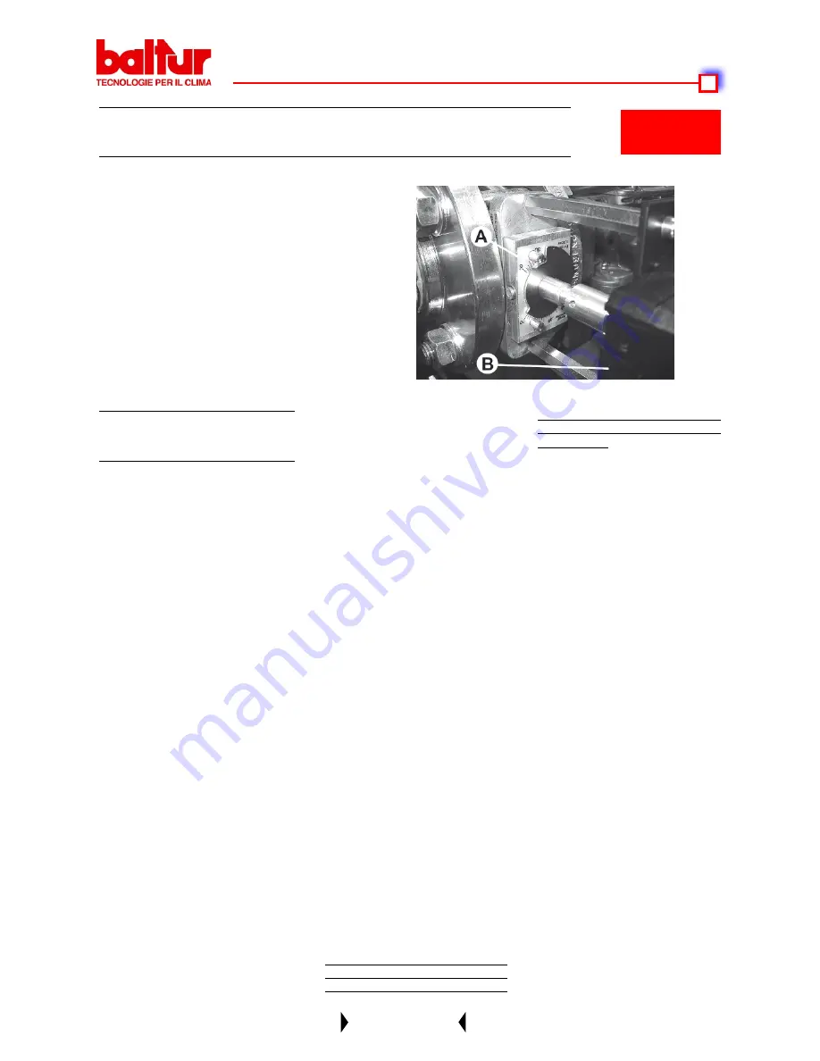
DETAIL OF GAS FEED REGULATOR THROTTLE VALVE WITH 

DUNGS SERVOMOTOR

A

  Gas throttle valve position reference index

B

  Gas modulation servomotor

N° 0002934220

Rev. 29/06/2004

1)  If  not  already  done  at  the  moment 

of  connecting  the  burner  to  the  gas 

pipeline, it is indispensable to carry 

out  a  purge  of  the  air  contained  in 
the pipeline. As a precaution, special 

care should be taken and doors and 

windows  should  be  opened.  Open 

the pipe union on the pipeline situa-
ted near the burner and then open a

  little the gas cut-off cock (or cocks). 

When  the  characteristic  odour  of 

gas  can  be  smelled,  close  the  cut-

off cock. Wait until the gas present in 

room has dispersed, and then recon-
nect  the  burner  to  the  gas  pipeline. 

Subsequently,  re-open  the  gas  cut-

off cock.

2) Check that there is water in the boi

-

ler and that the system’s gate valves 

are open.

3)  Check,  with  absolute  certainty  that 

the  discharge  of  combustion  pro-

ducts  can  take  place  freely  (boiler 

and  chimney  lock-gates  should  be 

open).

4)  Make  sure  that  the  voltage  of  the 

electric  line  to  which  the  burner  is 

to be connected,corresponds to that 

required by the burner and that the 

electrical  connections  (motor  and 
principle  line)  have  been  prepared 
to match the voltage rating available. 

Also check that all the electrical con

-

nections carried out on the spot are 

in accordance with our electric wiring 

diagram.

5) Make sure that the combustion head 

is  long  enough  to  enter  the  furnace 

to the extent specified by the boiler 

STARTING UP AND REGU-

LATION WITH METHANE

manufacturer. Check that the device 

which regulates the air on the com

-

bustion head is in the position consi-

dered necessary for the fuel delivery 

required  (air  passage  between  the 

disk and the head should be consi

-

derably reduced when the fuel deli

-

very is reduced; on the other hand, 

when the fuel delivery is fairly high, 

the  air  passage  between  the  disk 

and  the  head  should  be  relatively 

open).  See  Chapter  “Air  Regulation 
on the Combustion Head”.

6) Apply a manometer with an adequa

-

te scale (if the entity of pressure fo

-

recast allows it is preferable to use a 

column  of  water  instrument,  do  not 

use a pointer instrument for modera-
te pressure) to the pressure plug on 

the gas pressure switch.

7) Now insert the main switch. The con

-

trol box receives voltage in this way 

and  the  programmer  turns  on  the 
burner as described in Chapter “De-
scription  of  Operations”.  To  adjust 
the burner see the “MPA 22” electro-
nic  cam  instructions  in  the  attached 
manual code 0006080905.

8) After  adjusting  the  “minimum”,  (P) 

bring  the  burner  towards  maximum 

via  the  controls  on  the  MPA  22 

keypad. (see MPA 22 electronic cam 

instructions  in  the  attached  manual 
code 0006080905).

9)  We  recommend  that  you  carry  the 

out combustion tests with the appro

-

priate instrument at all intermediate

  points in the modulation range (from 

P1  to  P9);  also  check  the  gas  flow 

delivery rate via the meter.


It is essential to check, with a suita

-

ble  instrument,  that  the  percentage 
of    carbon  monoxide  (CO)  present 

in  the  fumes  does  not  exceed  the 
maximum permitted amount of 0.% 
(000 p.p.m.).

10)  Now  check  automatic  mode 

working of the modulation (see “MPA 

22” electronic cam instructions in en-
closed  manual  code  0006080905). 
In this mode the equipment receives 
the signal from the electronic modu-

lation adjuster RWF 40, if the burner 

is  modulating  version,  or  from  the 

thermostat  or  the  pressure  switch 

second  stage  if  the  burner  is  pro-

gressive two stage.

11) The air pressure switch has the job 

of bringing the control box to a safety 

shut down if the air pressure is not 

at  the  correct  value.  Therefore,  the 

air  pressure  switch  must  be  regu

-

lated in such a way as to intervene 

by  closing  the  contact  (foreseen  to 

by  closed  while  working)  when  the 

air  pressure  in  the  burner  has  rea-

ched a sufficient level. The pressure 

switch is self-controlled and therefo

-

re it must close the contact (fan stops 

and consequently there is an absen

-

ce of air pressure in the burner) if it 

does not, the control box will be in

-

serted (the burner remains at a sta-

dstill).It must be specified that if the 

contact is not closed during working 

(insufficient air pressure), the control 

box  will  carry  out  its  cycle,  but  the 

ignition transformer will not be inser

-

ted and the gas pilot valves will not 

open. Consequently, the burner will 

go  to  “shut  down”.  Check  that  the 

air pressure switch functions proper

-

ly  with  burner  at  minimum  delivery, 

increase the regulating value until it 
reaches  intervention  point  and  the 

burner  should  go  to  shut  down.  To 

Содержание btg 15 me

Страница 1: ...ruzioni per bruciatori modello Instruction for burners model Instrucci nes para quemadores modelos Mode d emploi brule r BTG15ME BTG20ME BTG28ME 0006081220_200703 0006081220_200703 IT GB SP FR IT GB S...

Страница 2: ......

Страница 3: ...rous accidents SP Antes de empezar a usar el quemador lea detenidamente el folleto ADVERTENCIAS DIRIGIDAS AL USUARIO PARA USAR CON SEGURIDAD EL QUEMADOR que va con el manual de instruc ciones y que co...

Страница 4: ...0 A1 2001 A2 2002 EN 55014 2 1997 A1 2001 EN 50366 2004 A1 2006 EN 61000 3 2 2000 A2 2005 Organo di Sorveglianza secondo la Direttiva Gas 90 396 CEE CE0085 DVGW Statement of Conformity We hereby decla...

Страница 5: ...002 EN 55014 2 1997 A1 2001 EN 50366 2004 A1 2006 EN 61000 3 2 2000 A2 2005 rgano de Vigilancia seg n la Directiva Gas 90 396 CEE CE0085 DVGW 0006080197 Rev 30 01 2007 D claration de conformit Nous d...

Страница 6: ...RIDUZIONE PRESSIONE GPL A DUE SALTI PER BRUCIATORE CALDAIA PRESSOSTATO ARIA CORRENTE DI IONIZZAZIONE 27 IRREGOLARIT DI FUNZIONAMENTO 28 SCHEMA IMPIANTO CON VAPORIZZATORE 65 SCHEMA ELETTRICO 66 ENGLIS...

Страница 7: ...IRR GULARIT S DE FONCTIONNEMENT 64 SCHEMA D INSTALLATION AVEC VAPORISATEUR 65 SCHEMA ECTRIQUE 66 ESPA OL 41 ADVERTENCIAS DIRGIDAS AL USUARIO 10 CARACTERISRICAS TECNICAS 14 APLICACI N DEL QUEMADOR A LA...

Страница 8: ...se si dovesse traslocare e lasciare l apparecchio assicurarsi sempre che il libretto accompagni l apparecchio in modo che possa essere consultato dal nuovo proprietario e o dall installatore Per tutti...

Страница 9: ...compromettere il buon funzionamento del bruciatore Per la prima messa in funzione dell apparecchio far effettuare da personale professionalmente qualificato le seguenti verifiche a il controllo della...

Страница 10: ...the owner moves and leaves the equipment make sure that the booklet always goes with the equipment so it can be consulted by the new owner and or installer For all equipment with optionals or kits inc...

Страница 11: ...law and regulations since incorrect installation may cause damage to person animals or things for which damage the manufacturer shall not can be held responsible Before installation it is advisable t...

Страница 12: ...sted se muda de casa y deja el aparato hay que asegurarse siempre de que el libro de instrucciones est siempre con el aparato para que pueda ser consultado por el nuevo propietario y o instalador Para...

Страница 13: ...an comprometer el buen funcionamiento del quemador La primera vez que se pone en funcionamiento el aparato el personal cualificado profesionalmente tiene que controlar a la estanqueidad en el tramo in...

Страница 14: ...appareil doit tre vendu ou transf r un autre propri taire ou si celui ci doit d m nager et laisser ce dernier toujours v rifier que la notice accompagne l appareil afin qu il puisse tre consulter par...

Страница 15: ...le bon fonctionnement du br leur Lors de la premi re mise en service de l appareil faire effectuer les v rifications suivantes par du personnel qualifi a le contr le de l tanch it de la partie interne...

Страница 16: ...A ELETTRICA ASSORBITA ABSORBED ELECTRICAL POWER POTENCIA EL CTRICA ABSORBIDA PUISSANCE LECTRIQUE ABSORB D 0 370 kW TRASFORMATORE D ACCENSIONE IGNITION TRANSFORMER TRANSFORMADOR DE ENCENDIDO TRANSFORMA...

Страница 17: ...have been obtained in compliance with EN 676 Nota los campos de trabajo se han obtenido conforme a las Normativas EN 676 Remarque Les plages de travail ont t obtenues conform ment aux Normes EN 676 CA...

Страница 18: ...ctor 5 Reference for disk head positioning 6 Combustion head 7 Disk head adjusting screw 8 Motor 9 Air pressure switch 10 Insulating gasket 11 Burner connection flange 12 Control box display 13 Air re...

Страница 19: ...penetri in camera di combustione come da disposizioni del costruttore della caldaia N 0002934100 Rev 10 02 2004 posizionare correttamente detta flangia affinch la testa di combu stione penetri nel foc...

Страница 20: ...one ai servomotori di regolazione del l erogazione aria gas che si portano al punto minimo P1 Se il termostato di caldaia o pressostato di 2 stadio lo consente regolato ad un valore di tem peratura o...

Страница 21: ...a pressio ne prevista lo consente preferibile utilizzare uno strumento a colonna d acqua non utilizzare per pressioni modeste strumenti a lancetta alla presa di pressione prevista sul pres sostato gas...

Страница 22: ...organi di regolazione ci si accerta dell in tervento del pressostato apertura di circuito che deve determinare l arre sto del bruciatore 13 Verificare l intervento del rilevatore di fiamma elettrodo a...

Страница 23: ...lizzare una chiusura dell aria sulla testa tale da richiedere una sensibile apertura della serranda aria che regola il flusso all uscita del ventilatore bruciatore ovviamente questa condizione si deve...

Страница 24: ...ZIONE DISCO FIAMMA E INDICE POSIZIONE DISCO FIAMMA 0 MIN 4 MAX per BTG 15ME 0 MIN 3 MAX per BTG 20ME 0 MIN 4 MAX per BTG 28ME 0002934190 X Distanza testa disco SCHEMA REGOLAZIONE TESTA DI COMBUSTIONE...

Страница 25: ...uendo la distanza X diminuisce il valore di emissione di NOx Regolare la distanza X sempre fra un valore min di 5 mm ed un valore max di 13 mm Elettrodo accensione Flangia attacco caldaia Entrata gas...

Страница 26: ...sizione di sicurezza in cui il bruciatore si dispone automaticamente quando qualche componente del bruciatore o dell impianto non sia efficiente occorre quindi accertarsi prima di sbloccare che la cau...

Страница 27: ...elettrodo di ionizzazione efficiente Occorre anche verificare che la scintilla dell elettrodo di accensione avvenga esclusivamente tra tra lo stesso ed il disco di lamiera forata Pu anche rendersi ne...

Страница 28: ...dette aperture almeno un terzo della superficie complessiva deve essere posta nella parte inferiore di parete esterna a filo pavimento 3 Esecuzioni dell impianto del gas liquido per assicurare corret...

Страница 29: ...io fino al blocco del bruciatore Ruotare quindi in senso antiorario la vite di circa 1 2 giro e ripetere l avvia mento del bruciatore per verificarne la regolarit Se il bruciatore si blocca nuovamente...

Страница 30: ...elettrodi 3 Controllare la taratura e il funzionamento del pressostato aria 1 Controllare il posizionamento dell elettrodo di controllo Controllare il valore della corrente di ionizzazione IRREGOLARIT...

Страница 31: ...e pi pe union in the pipeline in proximity to the burner to allow for easy di sas sembly of the burner and opening of the boiler door rectly po sition the flange so that the burner head enters the fur...

Страница 32: ...flame is detected by the relative control device an ionisation sensor positioned inside the flame The programming re lay goes beyond the shutdown position and powers the air gas delivery regula tion...

Страница 33: ...trument for modera te pressure to the pressure plug on the gas pressure switch 7 Now insert the main switch The con trol box receives voltage in this way and the programmer turns on the burner as desc...

Страница 34: ...arrest 13 Check the efficiency of the flame detector ionisation electrode by detaching the wire coming from the electrode and by turning on the bur ner The control box should carry out completely its...

Страница 35: ...be set to such position as to always obtain behind the disk a very high air pressure value It is advisable to regulate so as to have such air closure on the head as to require the opening of the air d...

Страница 36: ...R SCREW E DEFLECTOR DISK POSITION INDEX 0 MIN 4 MAX for BTG 15ME 0 MIN 3 MAX for BTG 20ME 0 MIN 4 MAX for BTG 28ME COMBUSTION HEAD ADJUSTMENT DIAGRAM BTG 15ME X Disk head distance X Min Max BTG 15ME 5...

Страница 37: ...ls Always adjust the distance X between the minimum value X 5 mm and the maximum value X 13 mm Ignition electrode Burner fixing flange Gas inlet X Min Max BTG 20ME 5 13 X Disk head distance N 00029351...

Страница 38: ...block po sition is a safety position reached by the burner automatically when some of the components of the burners or the plant do not work properly It is necessary to check then whether the cause t...

Страница 39: ...embly to exactly centre the electrodes one for switching on and one for flame detection to prevent these going to ground and blocking the burner Most of the components can be inspected by removing the...

Страница 40: ...5 of the room s area and a minimum of 0 5 m2 At least one third of the entire surface of these inlets must be located in the lower part of the external wall flush with the floor 3 Requirements for liq...

Страница 41: ...level slowly turn the central screw clockwise until the burner locks out Then give the screw a half turn anti clockwise and repeat burner start up to check for proper operation If the burner locks out...

Страница 42: ...operation of the air pressure switch 1 Check the position of the control electrode Check the valve of the ionisation current TYPE OF IRREGULARITY PROBABLE CAUSE RIMEDY The burner does not start The bu...

Страница 43: ...cas en dotaci n 0002934100 Nota Asegurarse de que el soporte de las boquillas penetre en la c mara de combusti n como indica el fabricante de la caldera el hogar lo que requiera el fabricante de la ca...

Страница 44: ...formador de encendido De esta ma nera el quemador est encendido en el punto de encendido P0 La presencia de la llama se detecta con el dispositivo de control sonda de ionizaci n metida en la llama El...

Страница 45: ...la adecuada a la toma de presi n pre vista en el presostato del gas si la presi n prevista lo permite es pre ferible utilizar un instrumento de co lumna de agua no utilizar para pre siones modestas in...

Страница 46: ...ectamente Operando con los respectivos rganos de re gulaci n es posible verificar el he cho de producirse la intervenci n del presostato apertura de circuito la que debe producir la desactivaci n del...

Страница 47: ...detr s del disco sea siempre alta Se aconseja regularlo para que comprima el aire en el cabezal de tal manera que la compuerta del aire que regula el flujo de aspiraci n del ventilador se abra ligera...

Страница 48: ...POSICI N DEL DISCO DEFLECTOR 0 MIN 4 MAX por BTG 15ME 0 MIN 3 MAX por BTG 20ME 0 MIN 4 MAX por BTG 28ME 0002934190 REGULACI N DEL CABEZAL DE COMBUSTI N BTG 15ME Entrada del gas Arandela de conexi n a...

Страница 49: ...ela de conexi n a la caldera Electrodo de encendido NOTA Disminuyendo la distancia X disminuye el valor de emisi n de NOx Regular la distancia x siempre entre el valor minimo 5mm y m ximo 13mm especif...

Страница 50: ...o antes de desbloquear el quemador hay que averiguar cu l es la causa que ha provocado el bloqueo y que no constituya una situaci n de peligro Las causas del bloqueo pueden tener un car cter transitor...

Страница 51: ...do de ionizaci n sea eficiente Hay que verificar tambi n que la chispa del electrodo de encendido se d exclusivamente entre el electrodo y el disco de chapa agujereada Puede que sea necesario limpiar...

Страница 52: ...laci n sin dispositivo de cierre realizado en paredes externas con una superficie por lo menos igual a 1 15 de la superficie en la planta del local con un m nimo de 0 5 m2 De estas aperturas por lo me...

Страница 53: ...ta que se bloquee el quemador A continuaci n girar media vuelta el tornillo en el sentido contrario de las agujas de reloj y repetir el arranque del quemador para controlar si est bien regulado Si el...

Страница 54: ...posici n de las puntas de los electrodos 3 Controlen el ajuste y el funcionamiento del pres stato del aire 1 Controlen la posici n del electrodo de control y el valor de la corriente de ionizaci n DEF...

Страница 55: ...G 2 Placer le joint isolant E sur le tube en interposant la corde F entre la bride et le joint 3 Enfin fixer le br leur la chaudi re l aide des goujons et des crous relatifs fournis avec l appareil N...

Страница 56: ...contr le correspondant sonde d io nisation immerg e dans la flamme Le relais programmateur passe la position de blocage et transmet la tension aux servomoteurs de r glage du d bit air DESCRIPTION DU...

Страница 57: ...crit au chapitre Descrip tion du fonctionnement Pour le r glage du br leur consulter les in structions relatives la came lectro nique MPA 22 indiqu es dans le manuel joint r f 0006080922 8 Apr s avoi...

Страница 58: ...ant le br leur le bo tier doit ex cuter compl te ment son cycle et deux secondes apr s la formation de la flamme d allumag il doit s arr ter en situa tion de blocage Il est n cessaire d effectuer cett...

Страница 59: ...l est conseill d effectuer le r glage de fa on r aliser une fermeture de l air sur la t te telle qu elle n cessite une ouverture sensible du volet d air qui r gule le d bit l aspiration du ventilateur...

Страница 60: ...MA REGLAGE TETE DE COMBUSTION BTG 20ME X Min Max BTG 20ME 5 13 N 0002934171 Rev 22 10 2004 Elettrodo accensione Flangia attacco caldaia Entrata gas X Distance t te disque Arriv e de gaz Electrode d al...

Страница 61: ...rode d allumage Bride de fixation chaudi re N 0002935180 Rev 18 12 2006 X Min Max BTG 28ME 40 68 1 Electrode d ionisation 2 Electrode d allumage 3 Disque flamme 4 M langeur 5 Tuyau de d part gaz SCHEM...

Страница 62: ...quent une fois d bloqu le br leur se remet fonctionner normalement Lorsque les blocages se r p tent 3 4 fois de suite ne pas insister mais rechercher la cause et y rem dier ou demander l intervention...

Страница 63: ...est aussi n cessaire que l tincelle de l lectrode d allumage ait lieu exclusivement entre celle ci et le disque de t le perfor e Il peut aussi tre n cessaire de nettoyer la t te de combustion Durant...

Страница 64: ...moins un tiers de la surface totale de ces ouvertures doit tre situ dans la partie inf rieure des murs ext rieurs au ras du sol 3 EXECUTION DE L INSTALLATION DE GAZ LIQUIDE AFIN DE GARANTIR UN FONCTIO...

Страница 65: ...ntrale jusqu au blocage du br leur Ensuite tourner la vis d environ 1 2 tour dans le sens contraire des aiguilles d une montre et red marrer le br leur afin de v rifier sa r gularit Si le br leur se b...

Страница 66: ...rodes 3 Contr ler le r glage et le fonctionnement du pressostat d air 1 Contr ler le positionnement de l lectrode de controle Contr ler la valeur du courant de ionisation DEFAUT CAUSE REMEDE Le br leu...

Страница 67: ...d en acier souder et rondelle en cuivre 4 Vanne de s curit 18 bar avec raccord en acier souder Avvertenze Il vaporizzatore considerato punto pericoloso pertanto va posto a distanza di sicurezza dai fa...

Страница 68: ......

Страница 69: ......

Страница 70: ......

Страница 71: ...La Casa por lo tanto se reserva cualquier posibilitad de modificati n de datos t cnicos y otras anotaciones Ce manuel rev t caract re purement indicatif La maison se reserve la possibilit de modifier...

Отзывы: