baltur 56510010 Скачать руководство пользователя страница 27

ACCENSIONE E REGOLAZIONE GAS 

METANO

REGOLAZIONE DELLA POTENZA DI PRIMA ACCENSIONE

• 

Inserire ora l’interruttore Interruttore MARCIA / ARRESTO del qua-

dro bruciatore; l’apparecchiatura di comando riceve così tensione 

ed il programmatore determina l’inserzione del bruciatore come de-

scritto nel capitolo “descrizione del funzionamento”. Durante la fase 

di preventilazione occorre accertarsi che il pressostato di controllo 

della pressione dell’aria effettui lo scambio. Se il pressostato aria 

non rileva la pressione sufficiente non viene inserito il trasformatore 

di accensione e nemmeno le valvole del gas, pertanto l’apparecchia

-

tura si arresta in “blocco”.

• 

Alla prima accensione possono verificarsi “blocchi” successivi dovuti 

a:

• 

Lo sfogo dell’aria dalla tubazione del gas non è stato eseguito cor-

rettamente e quindi la quantità di gas è insufficiente per consentire 

una fiamma stabile.

• 

Il “blocco” con presenza di fiamma può essere causato da instabi-

lità della stessa, per un rapporto aria/gas non corretto. Si rimedia 

variando la quantità di aria e/o di gas erogati in modo da trovare il 

corretto rapporto. Lo stesso inconveniente può essere causato da 

una non corretta distribuzione aria/gas nella testa di combustione; 

agendo  sul  dispositivo  di  regolazione  della  testa  di  combustione 

chiudere o aprire il passaggio dell’aria tra testa e diffusore gas.

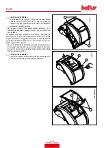
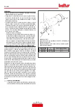
•  Correggere la portata d'aria erogata in primo stadio, agendo sulla 

vite/i (11) in corrispondenza del cuscinetto (12).


-

Rotazione oraria la portata d'aria aumenta 


-

Rotazione antioraria la portata d'aria diminuisce

REGOLAZIONE DELLA POTENZA IN SECONDO STADIO

•  Dopo aver completato la regolazione per la prima accensione, spe

-

gnere il bruciatore e chiudere il circuito elettrico che comanda l'inser-

zione del secondo stadio.
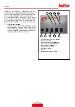
• 

Verificare che la camma di regolazione portata gas 

di secondo stadio del servomotore elettrico sia po

-

sizionata a 130°.

• 

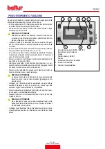
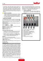
Inserire nuovamente il bruciatore chiudendo l'interruttore generale 

(1) sul pannello sinottico. Il bruciatore si accende e automaticamen-

te si porta in secondo stadio. Con l'ausilio degli appositi strumenti, 

provvedere alla regolazione dell'erogazione di aria e gas secondo la 

procedura di seguito descritta:

•  Per la regolazione della portata di gas agire sul regolatore di pressio

-

ne della valvola. Consultare le istruzioni relative al modello di valvola 

gas a singolo stadio installata.Evitare di mantenere in funzione il 

bruciatore se la portata termica bruciata è superiore a quella massi-

ma ammessa per la caldaia, onde evitare possibili danni alla stessa.

• 

Verificare con gli appositi strumenti i parametri di combustione (CO2 

MAX= 10% O2 MIN= 3% CO MAX=0,1%)

REGOLAZIONE DELLA POTENZA IN PRIMO STADIO

Terminata la regolazione del bruciatore in secondo stadio, riportare il 

bruciatore in primo stadio. Posizionare l'interruttore sul circuito stam-

pato in 1° stadio senza variare la regolazione della valvola gas già 

effettuata precedentemente.

• 

Regolare la portata di gas di 1° stadio al valore desiderato agendo, 

come descritto precedentemente.

• 

Regolare la portata di gas di 1° stadio al valore desiderato agendo, 

sul servomotore elettrico.

• 

Correggere se necessario l'erogazione di aria comburente operando 

sulle vite/viti (11) come descritto precedentemente.

• 

Verificare con gli appositi strumenti i parametri di combustione in 

primo stadio (CO2 MAX=10% O2 MIN= 3% CO MAX=0,1%)

•  Il pressostato aria ha lo scopo di impedire l’apertura delle valvole 

gas se la pressione dell’aria non è quella prevista. Il pressostato 

deve  quindi  essere  regolato  per  intervenire  chiudendo  il  contatto 

quando la pressione dell’aria nel bruciatore raggiunge il valore suffi-

ciente. Qualora il pressostato aria non rilevi una pressione superiore 

a quella di taratura, l’apparecchiatura esegue il suo ciclo ma non si 

inserisce il trasformatore d’accensione e non si aprono le valvole 

del gas e di conseguenza il bruciatore si arresta in “blocco”. Per 

accertare il corretto funzionamento del pressostato aria occorre, 

con  bruciatore  acceso,  in  prima  fiamma

, aumentarne 

il valore di regolazione fino a verificarne l’intervento a cui deve con-

seguire l’immediato arresto in “blocco” del bruciatore. Sbloccare il 

bruciatore, premendo l’apposito pulsante e riportare la regolazione 

del pressostato ad un valore sufficiente per rilevare la pressione di 

aria esistente durante la fase di pre-ventilazione.

TBML_ACC_REG_001

ITALIANO

25 / 42

0006160079_202008

Содержание 56510010

Страница 1: ...D GAS DIESEL BURNER TWO STAGE OPERATION ITALIANO Manuale istruzioni per l installazione l uso e la manutenzione IT Instruction manual for installation use and maintenance EN TBML 90P TBML 150P ISTRUZI...

Страница 2: ......

Страница 3: ...e TBML 90 150 P 17 Particolari pompa 18 Descrizione del funzionamento con combustibile liquido 19 Primo riempimento tubazione 21 Accensione e regolazione combustibile liquido 22 Descrizione del funzio...

Страница 4: ...LI La data di produzione dell apparecchio mese anno sono indicati sulla targa identificazione bruciatore presente sull apparecchio L apparecchio non adatto a essere usato da persone bambini compresi l...

Страница 5: ...e quelle parti che potrebbero essere potenziali fonti di pericolo AVVERTENZE PER L AVVIAMENTO IL COLLAUDO L USO E LA MANUTENZIONE L avviamento il collaudo e la manutenzione devono essere effet tuati e...

Страница 6: ...curezza vigenti condizione della categoria di sovratensione III Sguainare l isolante esterno del cavo di alimentazione nella misura strettamente necessaria al collegamento evitando cos che il filo pos...

Страница 7: ...mA 230 V 26 kV 48 mA Tensione 50hz 3N 400 V 10 3N 400 V 10 Tensione 60hz 3N 380 V 10 3N 380 V 10 Potenza elettrica 50hz kW 1 5 2 6 Potenza elettrica 60hz kW 1 5 3 0 Grado di protezione IP 40 IP 40 Ap...

Страница 8: ...essione combustibili gassosi 9 Viscosit combustibili liquidi 10 Potenza motore ventilatore 11 Tensione di alimentazione 12 Grado di protezione 13 Paese di costruzione e numeri di certificato di omolog...

Страница 9: ...AVORO 2 4 6 8 0 10 12 14 mbar 0002923001 400 500 600 700 800 900 1000 kW 15 1100 1200 1300 1400 1500 1600 1700 TBML 150P TBML 90P IMPORTANTE I campi di lavoro sono ottenuti su caldaie di prova rispond...

Страница 10: ...Elettrovalvola di sicurezza 8 Elettrovalvola 1 stadio 9 Cerniera 10 Servomotore regolazione aria gas 11 Pompa combustibile liquido 12 Quadro elettrico 13 Motore ventola QUADRO ELETTRICO 1 Apparecchiat...

Страница 11: ...A A1 A2 B B1 B2 C TBML 90P 700 330 370 580 380 200 1250 TBML 150P 700 330 370 580 380 200 1280 Modello E F I TBML 90P 180 178 280 TBML 150P 224 219 320 Modello M N TBML 90P M12 190 TBML 150P M12 235 I...

Страница 12: ...consigliata dal costruttore del generatore Posizionare sul canotto la guarnizione isolante 13 interponendo la corda 2 tra la flangia e guarnizione Posizionare sul cannotto la guarnizione isolante 13...

Страница 13: ...GIO CORPO VENTILANTE Posizionare le semicerniere presenti sulla chiocciola bruciatore in corrispondenza di quelle presenti sul gruppo testa Infilare il perno cerniera 10 nella posizione ritenuta pi id...

Страница 14: ...cordo di attacco al bruciatore Per ottenere il miglior funzionamento del regolatore di pressione opportuno che lo stesso sia applicato su tubazione orizzontale dopo il filtro Il regolatore di pression...

Страница 15: ...ve di sicurezza vigenti Per i collegamenti elettrici linea e termostati vedere il relativo sche ma elettrico Sguainare l isolante esterno del cavo di alimentazione nella misura strettamente necessaria...

Страница 16: ...nella direzione della freccia indicata in figura esercitando una leggera pressione con un utensile esempio cacciavite nella direzione delle freccce farlo scorrere per un breve tratto e separarlo dal...

Страница 17: ...o di sezione adatta per raggiungere la cisterna Evitare in ogni caso il collegamen to diretto del tubo di ritorno sul tubo di aspirazione E consigliabile coibentare convenientemente le tubazioni di as...

Страница 18: ...Servomotore regolazione aria 3 Ugello 2 stadio 4 Ugello 1 stadio 5 Valvola di sicurezza normalmente chiusa 6 Pompa 12 bar 7 Pompa 14 bar 8 Valvola normalmente chiusa A Aspirazione R Ritorno Perdita di...

Страница 19: ...TBML 150P interno 14 mm interno 16 mm Metri Metri Metri 1 30 40 1 5 35 45 2 35 45 2 5 40 50 3 40 50 7 9 8 4 H P 6 10 3 1 0002900740N2 IMPIANTO A CADUTA CON ALIMENTAZIONE DALLA SOMMIT DEL SER BATOIO 1...

Страница 20: ...B Per eventuali organi mancanti nelle tubazioni attenersi alle norme vigenti H Dislivello tra minimo livello in serbatoio e asse pompa L Per ogni gomito o saracinesca detrarre 0 25 m PARTICOLARI POMPA...

Страница 21: ...tore mette in rotazione la ventola che effettua un lavaggio con aria della camera di combustione e contemporaneamente la pompa del combustibile che determinano una circolazione nei condotti espellen d...

Страница 22: ...nsione del bruciatore CAUTELA AVVERTENZE La scelta degli ugelli in funzione della portata totale desiderata 2 ugelli in funzione deve essere effettuata tenendo conto dei valori di portata corrisponden...

Страница 23: ...un reci piente contenente olio lubrificante o gasolio non impiegare prodotti con bassa viscosit come petrolio kerosene ecc Premere ora sul pulsante 9 del quadro di comando per mettere in funzione il...

Страница 24: ...BUSTIONE Sia selezionato il tipo di combustibile corretto Verificare che gli ugelli applicati sul bruciatore siano adatti alla po tenzialit della caldaia e se necessario sostituirli con altri Per l ac...

Страница 25: ...basa sul colore della fiamma Consigliamo di regolare la combustione in modo da ottenere una fiamma morbida di colore arancio chiaro evitando fiamma rossa con presenza di fumo come pure fiamma bianca...

Страница 26: ...a serranda dell aria azionata da un apposito servomotore elet trico tenere presente che all arresto del bruciatore per intervento del termostato la serranda viene riportata dal servomotore nella posiz...

Страница 27: ...dere alla regolazione dell erogazione di aria e gas secondo la procedura di seguito descritta Per la regolazione della portata di gas agire sul regolatore di pressio ne della valvola Consultare le ist...

Страница 28: ...Se cos non fosse ridurre la portata di gas all accensione agendo sul freno della valvola FOTOCELLULA UV La fotocellula UV non rileva la luce del giorno o di una comune lampa da L eventuale verifica di...

Страница 29: ...Se cos non fosse ridurre la portata di gas all accensione agendo sul freno della valvola FOTOCELLULA UV La fotocellula UV non rileva la luce del giorno o di una comune lampa da L eventuale verifica di...

Страница 30: ...e cos ad ottenere un elevata pressione a monte del disco anche con le basse portate L elevata ve locit e turbolenza dell aria consente una migliore penetrazione della stessa nel combustibile e quindi...

Страница 31: ...TBML 90P 1 1 5 21 22 8 9 5 6 7 8 TBML 150P 1 1 5 20 21 7 8 3 4 8 9 REGOLAZIONE CAMME SERVOMOTORE SQN72 4D5 1 2 3 4 0002938170 1 Scala di riferimento 2 Indicatore di posizione 3 Perno inserzione ed es...

Страница 32: ...di il pulsante di sblocco un lampeggio veloce di colore rosso indicher che la funzione attiva analogamente per disattivare la funzione baster premere per almeno 3 secondi il pulsante di sblocco la com...

Страница 33: ...lvole combustibile Malfunzionamento rilevatore fiamma Difettosit nella taratura del bruciatore assenza di combustibile Mancata accensione difettosit trasformatore di accensione 3 lampeggi On Malfunzio...

Страница 34: ...cipale HS Contatto ausiliario rel ION Sonda di Ionizzazione K1 4 Rel Interni KL Fiamma bassa LK Serranda dell Aria LKP Posizione della serranda dell aria LP Pressostato aria LR Modulazione M Motore ve...

Страница 35: ...le operazioni di rimontaggio di centrare esattamente la testa di uscita gas rispetto agli elettrodi per evitare che gli stessi si trovino a massa con conseguente bloccaggio del bruciatore Effettuare...

Страница 36: ...etate le operazioni di manutenzione procedere con il rimon taggio della testa di combustione seguendo a ritroso il percorso sopra descritto dopo aver verificato la corretta posizione degli elet trodi...

Страница 37: ...NNO ANNO IMPIANTO ELETTRICO VERIFICA CONNESSIONI E SERRAGGIO MORSETTI ANNO ANNO INVERTER PULIZIA VENTOLA DI RAFFREDDAMENTO E SERRAGGIO MORSETTI ANNO ANNO SONDA CO PULIZIA E CALIBRAZIONE ANNO ANNO SOND...

Страница 38: ...8 04 28 81 29 56 30 29 31 00 31 70 32 38 33 05 33 70 5 5 6 00 17 66 19 00 20 40 21 63 22 80 23 92 24 98 26 00 26 98 27 93 28 84 29 73 30 59 31 43 32 25 33 04 33 82 34 58 35 33 36 05 36 77 6 00 6 50 19...

Страница 39: ...aspiratore al camino 2 Ugello inefficiente perch sporco o logoro 3 Presenza di acqua nel combustibile 4 Disco fiamma sporco 5 Eccesso di aria comburente 6 Passaggio d aria tra disco fiamma e diffu so...

Страница 40: ...di aria fredda 1 Sensore fiamma interrotto o sporco di fumo 2 Tiraggio insufficiente 3 Circuito del sensore fiamma interrotto nell apparecchiatura 4 Disco fiamma o diffusore sporchi 1 Interruzione ne...

Страница 41: ...3 Filtro combustibile sporco 4 Distanza e o dislivello negativo o ecces sivo fra cisterna e bruciatore oppure molte perdite accidentali curve gomiti strozzature ecc 5 Tubi flessibili deteriorati RIME...

Страница 42: ...SCHEMI ELETTRICI ITALIANO 40 42 0006160079_202008...

Страница 43: ...RCIAARRESTO S2 PULSANTE SBLOCCO S6 SELETTORE COMBUSTIBILE S7 PULSANTE CARICAMENTO SERBATOIO IMPIANTO SG INTERRUTTORE GENERALE T2 TERMOSTATO 2 STADIO TA TRASFORMATORE D ACCENSIONE TC TERMOSTATO CALDAIA...

Страница 44: ...ITALIANO 42 42 0006160079_202008...

Страница 45: ...P 17 Details of pumps 18 Description of operation with liquid fuel 19 First pipeline filling up 21 Ignition and adjustment with liquid fuel 22 Operation description with gaseous fuel 24 Natural gas ig...

Страница 46: ...25 C and 55 C The storage time is 3 years GENERAL WARNINGS The equipment production date month year is written on the bur ner identification plate located on the equipment The equipment cannot be use...

Страница 47: ...main switch Cut off the fuel supply using the shut off valve and remove the control wheels from their position Render harmless any potentially dangerous parts WARNINGS FOR START UP TEST USE AND MAINT...

Страница 48: ...tegory III Remove the external insulating seal of the supply pipe necessary for the connection preventing the cable to touch metal parts The use of any electrically fed components entails complying wi...

Страница 49: ...6 kV 48 mA 60 hz ignition transformer 26 kV 48 mA 230 V 26 kV 48 mA 50hz voltage 3N 400 V 10 3N 400 V 10 60hz voltage 3N 380 V 10 3N 380 V 10 50hz electrical power kW 1 5 2 6 60hz electrical power kW...

Страница 50: ...power 8 Gaseous fuel pressure 9 Liquid fuel viscosity 10 Fan motor power 11 Power supply voltage 12 Protection rating 13 Country of origin and numbers of certificate of approval 14 Manufacturing date...

Страница 51: ...110 2 185 110 3 120 60 OPERATING RANGE 2 4 6 8 0 10 12 14 mbar 0002923001 400 500 600 700 800 900 1000 kW 15 1100 1200 1300 1400 1500 1600 1700 TBML 150P TBML 90P IMPORTANT The working fields are obta...

Страница 52: ...lenoid valve 7 Safety solenoid valve 8 1st stage solenoid valve 9 Hinge 10 Air gas regulation servomotor 11 Liquid fuel pump 12 Electrical panel 13 Fan motor ELECTRICAL PANEL 1 Control box 2 Ignition...

Страница 53: ...A A1 A2 B B1 B2 C TBML 90P 700 330 370 580 380 200 1250 TBML 150P 700 330 370 580 380 200 1280 Model E F I TBML 90P 180 178 280 TBML 150P 224 219 320 Model M N TBML 90P M12 190 TBML 150P M12 235 ENGLI...

Страница 54: ...commended by the generator manufacturer Position the insulating gasket 13 on the sleeve by inserting the cord 2 between the flange and the gasket Position the insulating gasket 13 on the sleeve DANGER...

Страница 55: ...EM Position the half hinge on the burner scroll in line with those on the combustion head assembly Insert the hinge pin 10 in the position considered most suitable Connect the cables switch on and ion...

Страница 56: ...hment union To ensure optimal operation of the pressure regulator it should be applied to the horizontal pipe after the filter The gas pressure regulator must be adjusted when it is working at the max...

Страница 57: ...safety regulations Refer to the wiring diagram for electrical connections line and ther mostats Remove the external insulating seal of the supply pipe necessary for the connection preventing the cable...

Страница 58: ...distance following the direction on the arrow indicated in the figure exerting slight pressure with a tool e g a screwdriver following the arrows direction and slide it for a short distance to separa...

Страница 59: ...te cross section leading to the tank Avoid at all costs connecting directly the return pipe on the intake pipe It is advisable to properly insulate the intake and return pipes to pre vent cooling whic...

Страница 60: ...valve 2 Air regulation servomotor 3 2nd stage nozzle 4 1st stage nozzle 5 Normally closed safety valve 6 Pump 12 bars 7 Pump 14 bar 8 Normally closed valve A Intake R Return Pressure loss in hydraulic...

Страница 61: ...150P int 14 mm int 16 mm Meters Meters Meters 1 30 40 1 5 35 45 2 35 45 2 5 40 50 3 40 50 7 9 8 4 H P 6 10 3 1 0002900740N2 GRAVITY SYSTEM WITH FEED FROM THE TOP OF THE TANK 1 Serbatoio 3 Mesh filter...

Страница 62: ...s in force for any components missing in the pipe lines H Difference in level between minimum level in tank and pump axis L Deduct 0 25 m for each elbow or gate DETAILS OF PUMPS 2 3 5 4 1 7 1 6 AJ4 AJ...

Страница 63: ...switched on The motor turns the fan that carries out an air wash of the combustion chamber and at the same time the fuel pump that causes circulation in the ducts expelling any gas bubbles through th...

Страница 64: ...the whole of the burner ignition sequence CAUTION WARNINGS The selection of the nozzles in function of the desired total flow rate 2 nozzles in operation must be made accounting for the flow rate valu...

Страница 65: ...Dip the end of the flexible intake hose in a tin containing either lu bricant or diesel do not use low viscosity products such as petrol kerosene etc Now press key 9 on the control panel to start the...

Страница 66: ...elected Check that the nozzles fitted on the burner are suitable for the boiler capacity If necessary replace them with suitable ones To start the burner proceed as follows DANGER ATTENTION Prevent op...

Страница 67: ...le judge ment can be based on the colour of the flame We recommend that the adjustment is performed so as to obtain a soft light orange flame avoid red flames with smoke and white flames with an exces...

Страница 68: ...an ON OFF valve The air damper is activated by a dedicated electric servomotor keep in mind that when the burner is locked out because the ther mostat is tripped the servomotor returns the air damper...

Страница 69: ...end to the regulation of the air and gas flow according to the procedures subsequently described To regulate the gas flow operate the valve pressure regulator Con sult the instructions related to the...

Страница 70: ...onsumption read on the meter must be Qstart 90 360 0 25 m If this does not occur reduce the flow of gas to the ignition through the brake of the valve UV PHOTOCELL The UV photocell does not detect day...

Страница 71: ...onsumption read on the meter must be Qstart 90 360 0 25 m If this does not occur reduce the flow of gas to the ignition through the brake of the valve UV PHOTOCELL The UV photocell does not detect day...

Страница 72: ...ases the pressure upstream of the disk also with low flow rates The high speed and turbulence of the air provides for its greater penetration into the fuel and therefore an excellent mixture and flame...

Страница 73: ...5 SS TBML 90P Monarch type 60 PLP TBML 150P A B C D E TBML 90P 1 1 5 21 22 8 9 5 6 7 8 TBML 150P 1 1 5 20 21 7 8 3 4 8 9 SERVOMOTOR CAMS ADJUSTMENT SQN72 4D5 1 2 3 4 0002938170 1 Reference scale 2 Pos...

Страница 74: ...or at least 3 seconds A quick red flashing indicates that the function is active Likewise hold the reset button down for at least 3 seconds to deactivate the function the switching will be indicated w...

Страница 75: ...n No flame at the end of the safe ignition time TSA Fuel valves malfunctioning Flame detector malfunctioning Incorrect burner calibration no fuel No ignition faulty ignition transformer 3 blinks On Fa...

Страница 76: ...Auxiliary contactor relay ION__tab_Ionisation probe K1 4 Internal Relays KL Low flame LK Air damper LKP Air damper position LP Air pressure switch LR Modulation M Fan motor MS Synchronous motor NL Ra...

Страница 77: ...careful during the reassembly operations to exactly centre the gas diffuser with respect to the electrodes making sure that they are not earthed which would result in the locking of the burner Analyse...

Страница 78: ...e arrow Having completed the maintenance work replace the combustion head following in reverse order the operations described above after having checked the correct position of ignition and ionisation...

Страница 79: ...S BALL JOINTS CHECK OF ANY WEAR COMPONENT LUBRICATION YEAR YEAR ELECTRICAL SYSTEM CHECK OF CONNECTIONS AND TERMINAL TIGHTENING YEAR YEAR INVERTER COOLING FAN CLEANING AND TERMINAL TIGHTENING YEAR YEAR...

Страница 80: ...6 44 27 25 28 04 28 81 29 56 30 29 31 00 31 70 32 38 33 05 33 70 5 5 6 00 17 66 19 00 20 40 21 63 22 80 23 92 24 98 26 00 26 98 27 93 28 84 29 73 30 59 31 43 32 25 33 04 33 82 34 58 35 33 36 05 36 77...

Страница 81: ...low 1 Excessive draught only when there is an extractor in the chimney 2 Nozzle inefficient because dirty or worn 3 Water in the fuel 4 Dirty flame disk 5 Too much combustion air 6 Air passage between...

Страница 82: ...Flame sensor off or soiled with smoke 2 Insufficient draught 3 Flame sensor circuit interrupted in the equipment 4 Dirty flame disk and diffuser 1 Ignition circuit severed 2 The ignition transformer...

Страница 83: ...n the pipes 3 Dirty fuel filter 4 Excessive distance and or difference in level between the tank and the burner or numerous accidental leakages elbows curves bottlenecks etc 5 Deteriorated flexible pi...

Страница 84: ...WIRING DIAGRAMS ENGLISH 40 42 0006160079_202008...

Страница 85: ...SWITCH S1 START STOP SWITCH S2 RELEASE BUTTON S6 FUEL SWITCH S7 TANK SYSTEM FILLING BUTTON SG MAIN SWITCH T2 2ND STAGE THERMOSTAT TA IGNITION TRANSFORMER TC BOILER THERMOSTAT TS SAFETY THERMOSTAT U1...

Страница 86: ...ENGLISH 42 42 0006160079_202008...

Страница 87: ......

Страница 88: ...Il presente catalogo riveste carattere puramente indicativo La casa pertanto si riserva ogni possibilit di modifica dei dati tecnici e di quant altro in esso riportato Information contained in this c...

Отзывы: