ENGLISH
20 / 44
0006160028_201510
FIRST PIPELINE FILLING UP
After checking that the protective plastic caps on the pump fittings
have been removed, proceed as follows:
•
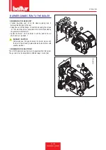
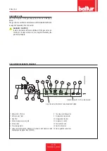
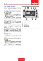
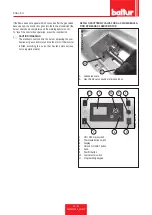
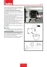
Turn to "on" position the switch -1 on the mimic panel of the bur-
ner making sure that the thermostat line switch -2 is set to "O".
•
Make sure the line voltage is the same as indicated in the iden-
tification plate of the burner.
DANGER / CAUTION
To positively determine the direction of rotation, wait until
the fan turns very slowly because it is quite easy to misin-
terpret the direction of rotation.
•
The rotation direction can be determined also looking at the
direction of fan rotation through the inspection window on the
back of the scroll.
•
If it is necessary to change the direction of rotation, invert two
phases of the line input terminals (L1_L2_L3)
•
To start up the motor, close the remote control switch manually
(by pressing on the mobile part) for a few seconds and watch
the sense of rotation of the fan.
• Detach, if already attached, the flexible hoses from the intake
and return pipes.
•
Dip the end of the suction hose into a vessel containing either
lubrication oil or diesel (do not use low viscosity products such
as petrol, kerosene, etc.).
•
Now press key (9) on the control panel to start the motor and
the pump. Wait until the pump has sucked an amount of lubri-
cant equal to 1 or 2 glasses, then stop. This operation will pre-
vent the pump from operating dry and will increase the suction
power.
DANGER / CAUTION
Pump operating at 2800 r.p.m. must not work dry otherwise
they will jam (seizure) within a very short time.
• Attach the flexible hose to the intake pipe and open any gate
valves fitted on this pipe and any other shut-off element on the
fuel pipes.
•
Press button (9) again to start up the pump that extracts the fuel
from the tank.
When you see the fuel coming out of the return line (not yet connected), stop.
DANGER / CAUTION
If the pipe is long, it may be necessary to bleed the air out
through the cap; if the pump is not fitted with a cap, remove
the pressure gauge connector cap.
• Connect the return flexible hose to the return pipe and open the
gates fitted on this pipe. Now the burner is ready for lighting up.
1
2
10
3
4
9
11
5
display_TBML_ME
1 ON / OFF main switch.
2 Thermostatic line switch
3 Display
4 Unlock or RESET button
5 Fuse.
9 Fuel fill button
10 Fuel selector switch
11 Programming keypad
Содержание 56460010
Страница 2: ......
Страница 40: ...SCHEMI ELETTRICI ITALIANO 38 44 0006160028_201510...
Страница 41: ...ITALIANO 39 44 0006160028_201510...
Страница 42: ...ITALIANO 40 44 0006160028_201510...
Страница 43: ...ITALIANO 41 44 0006160028_201510...
Страница 44: ...BT1 BA BP I1 I2 I3 I4 ITALIANO 42 44 0006160028_201510...
Страница 46: ...ITALIANO 44 44 0006160028_201510...
Страница 84: ...ENGLISH 38 44 0006160028_201510 WIRING DIAGRAMS...
Страница 85: ...ENGLISH 39 44 0006160028_201510...
Страница 86: ...ENGLISH 40 44 0006160028_201510...
Страница 87: ...ENGLISH 41 44 0006160028_201510...
Страница 88: ...ENGLISH 42 44 0006160028_201510 BT1 BA BP I1 I2 I3 I4...
Страница 90: ...ENGLISH 44 44 0006160028_201510...
Страница 91: ......


