background image

ENGLISH

32 / 44

0006160028_201510

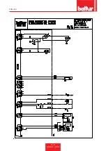
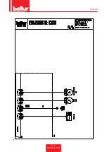
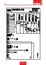
MAINTENANCE

Analyse combustion gases and check that the emission values 

are correct at least once a year, in compliance with current law.

Carry out the following operations at the end of the heating sea-

son:

• 

Clean air dampers, the air pressure switch with pressure port 

and the relevant pipe (if fitted).

• 

Check the electrode condition. Replace them, if necessary.

• 

Clean the photocell. Replace it, if necessary.

• 

Have the burner and the chimney cleaned by specialised per-

sonnel (stove repairer); a clean burner is more efficient, lasts 

longer and is quieter.

•  Check that the fuel filter is clean. Replace it, if necessary.

• 

Check that all components of the combustion head are in good 

condition, have not been deformed and are free from deposi-

ts deriving from the installation environment and/or from poor 

combustion.

• 

Analyse combustion gases and check emissions values.

DANGER / CAUTION

When closing the burner, gently pull the two ignition cables 

towards the electrical panel, putting them slightly in tension, 

then arrange them in their housing on the scroll. This will 

ensure that the two cables do not get damaged by the fan 

during burner operation.

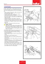
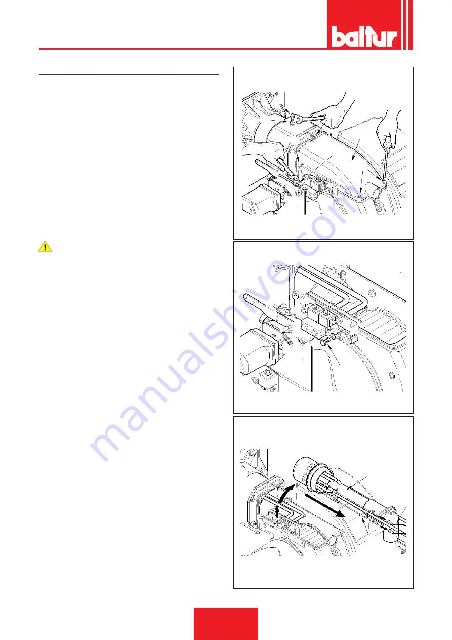
If it is necessary to clean the outside of the combustion head, take 

out its components according to the procedure described:

• 

Disconnect the photocell and the air pressure switch pipe from 

the upper lid of the burner.

• 

Disconnect diesel fuel pipe -24 from its connector (be careful 

of drips).

• 

Loosen screws 5 -6 and remove the cover -11 .

• 

After having loosened the nut -9 remove the locking screw (32) 

of the mixer unit.

• 

Remove the screw -16 and its washer placed on the outside of 

the burner scroll.

• 

Slightly lift the mixing unit -17, and then completely pull out the 

unit in the direction indicated by the arrow, after removing the 

ignition cables -10 from the respective electrodes.

• 

After completing the maintenance operations proceed with the 

assembly of the mixing unit by carrying out the above opera-

tions in reverse order, after checking that the ignition electrodes 

and the deflector disk are correctly positioned.

24

11

6

6

6

32

9

0002937470

16

0002937480

17

Содержание 56460010

Страница 1: ...ICA TWO STAGE ELECTRONIC MODULATING GAS DIESEL BURNER ITALIANO Manuale istruzioni per l installazione l uso e la manutenzione IT Installation use and maintenance instruction manual EN TBML 50 ME ISTRU...

Страница 2: ......

Страница 3: ...amento con combustibile liquido pag 18 Primo riempimento tubazione pag 20 Accensione e regolazione combustibile liquido pag 21 Particolari pompa pag 22 Descrizione del funzionamento con combustibile g...

Страница 4: ...icircolazione esterna fumi rispettano i requisiti minimi imposti dalle Direttive e Regolamenti europei 2009 142 CE UE 2016 426 D A G R A G 2014 30 CE C E M 2014 35 CE D B T 2006 42 CE D M e sono confo...

Страница 5: ...o mese anno sono in dicati sulla targa identificazione bruciatore presente sull appa recchio L apparecchio non adatto a essere usato da persone bambini compresi le cui capacit fisiche sensoriali o men...

Страница 6: ...e quelle parti che potrebbero essere poten ziali fonti di pericolo AVVERTENZE PER L AVVIAMENTO IL COLLAUDO L USO E LA MANUTENZIONE L avviamento il collaudo e la manutenzione devono essere ef fettuati...

Страница 7: ...chio indicata in targa Accertarsi che la sezione dei cavi dell impianto sia idonea alla potenza assorbita dall apparecchio Non consentito l uso di adattatori prese multiple e o prolun ghe per l alimen...

Страница 8: ...30 V TENSIONE 50Hz 3N 400 V 10 TENSIONE 60Hz 3N 380 V 10 POTENZA ELETTRICA 50Hz kW 1 1 POTENZA ELETTRICA 60Hz kW 1 1 GRADO DI PROTEZIONE IP 40 APPARECCHIATURA LME 73 RILEVAZIONE FIAMMA Fotocellula UV...

Страница 9: ...mbustibili gassosi 8 Pressione combustibili gassosi 9 Viscosit combustibili liquidi 10 Potenza motore ventilatore 11 Tensione di alimentazione 12 Grado di protezione 13 Paese di costruzione e numeri d...

Страница 10: ...PO DI LAVORO TBML 50 ME MC 10 8 6 4 2 0 100 200 300 400 500 600 kW 0002922890 mbar IMPORTANTE I campi di lavoro sono ottenuti su caldaie di prova rispondenti alla nor ma EN267 per i combustibili liqui...

Страница 11: ...A2 A E F C B6 D B1 B 0002471410N2 Modello A A1 A2 B B1 B6 C TBML 50 ME 640 270 370 455 325 160 1020 Modello D min D max E F I L min L max TBML 50 ME 170 340 156 152 260 225 300 Modello M N TBML 50 ME...

Страница 12: ...olazione aria 10 Pompa bruciatore 11 Quadro elettrico 12 Motore 13 Targa identificazione bruciatore 10 11 12 1 2 3 8 6 9 4 7 5 0002471410N1 13 QUADRO ELETTRICO 1 Apparecchiatura 2 Pressostato aria 3 T...

Страница 13: ...e del generatore Fissare il bruciatore 18 alla caldaia 1 tramite i prigionieri le rondelle e i relativi dadi in dotazione 7 PERICOLO ATTENZIONE Sigillare completamente con materiale idoneo lo spazio t...

Страница 14: ...A GAS M M 12 10 9 14 11 13 8 4 7 6 5 3 2 1 0002910950N2 A CURA DELL INSTALLATORE RAMPA GAS FORNITA DAL COSTRUTTORE 1 Valvola di intercettazione manuale 2 Giunto antivibrante 3 Filtro gas 4 Pressostat...

Страница 15: ...o di ritorno 8 Dispositivo automatico inter cettazione a bruciatore fermo 9 Valvola unidirezzionale 10 Valvola di fondo H L Complessiva Metri Metri i 14 mm 1 30 1 5 35 2 35 2 5 40 3 40 Quota P 3 5 m M...

Страница 16: ...tive di sicurezza vigenti Per i collegamenti elettrici linea e termostati vedere il relativo schema elettrico Sguainare l isolante esterno del cavo di alimentazione nella misura strettamente necessari...

Страница 17: ...della freccia in dicata in figura esercitando una leggera pressione con un utensile esempio cacciavite nella direzione delle freccce farlo scorrere per un breve tratto e separarlo dal coperchio Per un...

Страница 18: ...Evitare in ogni caso il collega mento diretto del tubo di ritorno sul tubo di aspirazione E consigliabile coibentare convenientemente le tubazioni di aspi razione e di ritorno per evitare raffreddamen...

Страница 19: ...ervomotore regolazione aria 3 Ugello 2 stadio 4 Ugello 1 stadio 5 Valvola di sicurezza normalmente chiusa 6 Pompa 12 bar 7 Valvola normalmente chiusa A Aspirazione R Ritorno Perdita di carico circuito...

Страница 20: ...della camera di combustione e contemporaneamente la pom pa del combustibile che determinano una circolazione nei condotti espellendo attraverso il ritorno eventuali bolle di gas Questa fase di prelava...

Страница 21: ...ale deside rata 2 ugelli in funzione deve essere effettuata tenendo conto dei valori di portata corrispondenti alla pressione di lavoro di 12 bar del gasolio Sostituendo gli ugelli possibi le variare...

Страница 22: ...gasolio non impiegare prodotti con bassa viscosit come petrolio kerosene ecc Premere ora sul pulsante 9 del quadro di comando per met tere in funzione il motore stesso e quindi la pompa Attendere che...

Страница 23: ...la caldaia Accertarsi che la testa di combustione penetri nel focolare nella misura richiesta dal costruttore della caldaia Verificare che il dispositivo di chiusura aria sulla testa di combustione si...

Страница 24: ...Ritorno con grano di by pass interno 5 Aspirazione 6 Mandata all ugello 7 Attacco vuotometro 1 8 G 7 1 Attacco vuotometro e grano di BY PASS interno CAUTELA AVVERTENZE La pompa viene pre regolata ad...

Страница 25: ...e delle valvole principale e sicurezza si disinserisce il trasformatore d accensione Il bruciatore cos acceso al punto di accensione La presenza della fiamma viene rilevata dal relativo dispositivo di...

Страница 26: ...ente del gas e se presente l inverter del motore ventola secondo una curva di lavoro avente dieci punti impostati vedi tabella regolazione curva PARTICOLARE VALVOLAA FARFALLA DI REGOLAZIONE EROGAZIONE...

Страница 27: ...ti come da nostro schema elettrico Accertarsi che la testa di combustione abbia lunghezza suffi ciente per penetrare nel focolare nella misura richiesta dal co struttore della caldaia Verificare che i...

Страница 28: ...un zionamento automatico della modulazione portando l apparec chiatura in posizione AUTOMATICA In questo modo la mo dulazione inserita esclusivamente con il comando automatico della sonda di caldaia S...

Страница 29: ...ella a cui regolato La regolazione dei pressostati di minima e di massima deve quindi avvenire all atto del collaudo del bruciatore in funzione della pres sione che si riscontra di volta in volta Prec...

Страница 30: ...l termostato facendola corrispondere a quella del termometro REGOLAZIONE ARIA SULLA TESTA DI COMBUSTIONE La testa di combustione dotata di un dispositivo di regolazione che permette di aprire o chiude...

Страница 31: ...gelli 6 Canotto porta ugelli UGELLI CONSIGLIATI MONARCH tipo 30 HV Dopo aver montato gli ugelli verificare il corretto posizionamento di elettrodi e disco secondo le quote indicate in mm E opportuno e...

Страница 32: ...ali vigenti Esecuzione impianto del gas propano liquido per assicurare un corretto funzionamento in sicurezza La gassificazione naturale da batteria di bombole o serbatoio utilizzabile solo per impian...

Страница 33: ...ilizzatore Riduttore di 2 salto Uscita 30 mbar Portata il doppio del massimo richiesto dall utilizzatore Filtro a Y Filtro Filtro Presa di pressione Riduttore di 2 salto Uscita 30 mbar Portata il dopp...

Страница 34: ...e verso il quadro elettrico mettendoli in leggera tensione i due cavi di accensione quindi sistemarli nelle apposite sedi sulla chiocciola Questo eviter che i due cavi venga no danneggiati dalla vento...

Страница 35: ...I SNODI SFERICI GIOCHI LUBRIFICAZIONE CONTROLLO EVENTUALI GIOCHI ANNO ANNO TUBI FLESSIBILI SOSTITUZIONE N A 5 ANNI LINEA COMBUSTIBILE GAS GASOLIO FILTRO POMPA PULIZIA ANNO ANNO FILTRO DI LINEA PULIZIA...

Страница 36: ...24 20 95 21 63 22 30 22 95 23 57 24 19 24 78 4 50 5 00 15 90 17 00 18 03 19 00 19 93 20 82 21 67 22 48 23 27 24 04 24 78 25 49 26 19 26 87 27 54 5 00 5 5 17 49 18 70 19 83 20 90 21 92 22 90 23 83 24 7...

Страница 37: ...un aspiratore al camino 2 Ugello inefficiente perch sporco o logoro 3 Presenza di acqua nel combustibile 4 Disco fiamma sporco 5 Eccesso di aria comburente 6 Passaggio d aria tra disco fiamma e diffus...

Страница 38: ...i aria fredda 1 Fotoresistenza interrotta o sporca di fumo 2 Tiraggio insufficiente 3 Circuito del rilevatore fiamma interrotto nell apparecchiatura 4 Disco fiamma o diffusore sporchi 1 Interruzione n...

Страница 39: ...3 Filtro combustibile sporco 4 Distanza e o dislivello negativo o eccessivo fra cisterna e bruciatore oppure molte perdite accidentali curve gomiti strozzature ecc 5 Tubi flessibili deteriorati RIMEDI...

Страница 40: ...SCHEMI ELETTRICI ITALIANO 38 44 0006160028_201510...

Страница 41: ...ITALIANO 39 44 0006160028_201510...

Страница 42: ...ITALIANO 40 44 0006160028_201510...

Страница 43: ...ITALIANO 41 44 0006160028_201510...

Страница 44: ...BT1 BA BP I1 I2 I3 I4 ITALIANO 42 44 0006160028_201510...

Страница 45: ...MV MOTORE VENTOLA N1 REGOLATORE ELETTRONICO PA PRESSOSTATO ARIA Pm PRESSOSTATO DI MINIMA S1 INTERRUTTORE MARCIAARRESTO S6 SELETTORE COMBUSTIBILE S7 PULSANTE CARICAMENTO SERBATOIO IMPIANTO S24 INTERRU...

Страница 46: ...ITALIANO 44 44 0006160028_201510...

Страница 47: ...scription of operation with liquid fuel pag 18 First pipeline filling up pag 20 Ignition and adjustment with liquid fuel pag 21 Pump parts pag 22 Operation description with gaseous fuel pag 23 Natural...

Страница 48: ...recirculation respect the minimal regulations of the European Directives and Regulations 2009 142 CE UE 2016 426 D A G R A G 2014 30 CE C E M 2014 35 CE D B T 2006 42 CE D M and have been designed and...

Страница 49: ...ure betwe en 10 C and 40 C The storage time is 3 years GENERAL INSTRUCTIONS The equipment production date month year is written on the burner identification plate located on the equipment The device i...

Страница 50: ...d remove the control wheels from their position Render harmless any potentially dangerous parts INSTRUCTIONS FOR START UP INSPECTION USE AND MAINTENANCE Start up inspection and maintenance of the equi...

Страница 51: ...on the data plate Make sure that the system cable cross section is suitable for the power absorbed by the equipment The use of adaptors multiple plugs and or extension leads to supply power from the m...

Страница 52: ...MER 26 kV 48 mA 230 V 60 Hz IGNITION TRANSFORMER 26 kV 48 mA 230 V VOLTAGE 50Hz 3N 400 V 10 VOLTAGE 60Hz 3N 380 V 10 50Hz ELECTRICAL POWER kW 1 1 60Hz ELECTRICAL POWER kW 1 1 DEGREE OF PROTECTION IP 4...

Страница 53: ...rial number 6 Liquid fuel power 7 Gas fuel power 8 Gas fuel pressure 9 Liquid fuel viscosity 10 Fan motor power 11 Power supply voltage 12 Protection rating 13 Country of manufacture and homologation...

Страница 54: ...emissions in mg kWh diesel fuel 1 250 110 2 185 110 3 120 60 OPERATING RANGE TBML 50 ME MC 10 8 6 4 2 0 100 200 300 400 500 600 kW 0002922890 mbar IMPORTANT The working fields are obtained from test...

Страница 55: ...ALL DIMENSIONS N L 45 45 M I I A1 A2 A E F C B6 D B1 B 0002471410N2 Model A A1 A2 B B1 B6 C TBML 50 ME 640 270 370 455 325 160 1020 Model D min D max E F I L min L max TBML 50 ME 170 340 156 152 260 2...

Страница 56: ...8 1st Stage solenoid valve 9 Air regulation servomotor 10 Burner pump 11 Electrical panel 12 Motor 13 Burner identification plate 10 11 12 1 2 3 8 6 9 4 7 5 0002471410N1 13 ELECTRICAL PANEL 1 Control...

Страница 57: ...e extent requested by the generator manufacturer Fasten the burner 18 to the boiler 1 with the stud bolts wa shers and nuts provided 7 DANGER CAUTION Completely seal the gap between the burner sleeve...

Страница 58: ...principle GAS BURNER SCHEMATIC DIAGRAM M M 12 10 9 14 11 13 8 4 7 6 5 3 2 1 0002910950N2 RESPONSIBILITY OF THE INSTALLER GAS TRAIN SUPPLIED BY THE MANUFACTURER 1 Manual shut off valve 2 Vibration proo...

Страница 59: ...er 4 Pump 6 Suction pipe 7 Return pipe 8 Automatic shut off device with burner off 9 Unidirectional valve 10 Foot valve H Total L Meters Meters i 14 mm 1 30 1 5 35 2 35 2 5 40 3 40 Value P 3 5 m Max I...

Страница 60: ...ance with current safety regulations Refer to the wiring diagram for electrical connections line and thermostats Unsheathe the external insulating cover of the power cable to the necessary extent for...

Страница 61: ...sparent door 7 for a short distance following the direction on the arrow in dicated in the figure exerting slight pressure with a tool e g a screwdriver following the arrows direction and slide it for...

Страница 62: ...connect the return pipe directly to the intake pipe It is advisable to properly insulate the intake and return pipes to prevent cooling which would affect the unit s efficiency Pipe dia meters to be s...

Страница 63: ...NE DIAGRAM OF HYDRAULIC CIRCUIT 1 Foot valve 2 Air regulation servomotor 3 2nd stage nozzle 4 1st stage nozzle 5 Safety valve normally closed 6 Pump 12 bar 7 Valve normally closed A Intake R Return Hy...

Страница 64: ...air wash of the combu stion chamber and at the same time the fuel pump that causes circulation in the ducts expelling any gas bubbles through the re turn valve This pre washing phase ends with the op...

Страница 65: ...f the nozzles in relation to the desired total flow rate 2 nozzles in operation must be made taking into consideration the flow rate values that correspond to the diesel operating pressure of 12 bar R...

Страница 66: ...into a vessel containing either lubrication oil or diesel do not use low viscosity products such as petrol kerosene etc Now press key 9 on the control panel to start the motor and the pump Wait until...

Страница 67: ...ces Check if there is fuel in the tank and water in the boiler Check that combustion head penetrates the combustion cham ber by the measure requested by the manufacturer of the boiler Check that the a...

Страница 68: ...ure adjustment screw AN77 10 20bars 4 1 Return with internal BY PASS dowel 5 Suction 6 Delivery to nozzle 7 Vacuum gauge connector 1 8 G 7 1 Vacuum gauge connector and internal BY PASS dowel CAUTION W...

Страница 69: ...supply is regulated by the butterfly gas valve Three seconds after the valves main and safety come on the ignition transformer goes off Thus the burner is ignited at the igni tion point Flame presenc...

Страница 70: ...the burner activating the com bustion air gas servomotor and the fan motor if the inverter is fitted according to a curve that has ten points set see curve regulation table DETAIL OF BUTTERFLY VALVE...

Страница 71: ...ormed properly as illustrated in our wiring diagram Make sure that the combustion head is long enough to enter the furnace following the measure specified by the boiler ma nufacturer Check that the ai...

Страница 72: ...eck for the efficiency of automatic modulation operation by switching the ETAMATIC apparatus to the AUTO MATIC position With this setting modulation will start only by using the automatic control of t...

Страница 73: ...djustment of minimum and maximum pressure values on the pressure switches must be performed when testing the burner on the basis of the pressure measured in each case The triggering opening of the cir...

Страница 74: ...AIR REGULATION ON THE COMBUSTION HEAD The combustion head has a regulation device that allows the air passage between the disc and the combustion head to be opened or closed You are thus able to obtai...

Страница 75: ...r 3 Flame disk 4 Ignition electrode 5 Nozzles 6 Nozzle holder RECOMMENDED NOZZLES MONARCH 30 HV type After installing the nozzles make sure that the electrodes and disk are correctly positioned accord...

Страница 76: ...lation slots on external walls without closing devices in ac cordance with the regulations in force Performance of the LPG system to ensure correct and safe operation Natural gasification from a cylin...

Страница 77: ...r Flow rate double the maximum required by the user 2nd step reducer Output 30 mbar Flow rate double the maximum required by the user Y filter Filter Filter Pressure intake 2nd step reducer Output 30...

Страница 78: ...es towards the electrical panel putting them slightly in tension then arrange them in their housing on the scroll This will ensure that the two cables do not get damaged by the fan during burner opera...

Страница 79: ...r s indications were provided YEAR YEAR LEVERS STRAP SYSTEM BALL JOINTS BACKLASH LUBRICATION CHECK FOR POSSIBLE BACKLASH YEAR YEAR HOSES REPLACEMENT N A 5 YEARS FUEL LINE GAS DIESEL PUMP FILTER CLEANI...

Страница 80: ...4 50 14 31 15 30 16 22 17 10 17 94 18 73 19 50 20 24 20 95 21 63 22 30 22 95 23 57 24 19 24 78 4 50 5 00 15 90 17 00 18 03 19 00 19 93 20 82 21 67 22 48 23 27 24 04 24 78 25 49 26 19 26 87 27 54 5 00...

Страница 81: ...only when there is an extractor in the chimney 2 Nozzle inefficient because dirty or worn 3 Water in the fuel 4 Dirty deflector disk 5 Too much combustion air 6 Air passage between deflector disk and...

Страница 82: ...or cold air infiltration 1 Photoresistance severed or fouled with smoke 2 Insufficient draught 3 Flame detector circuit interrupted in the equipment 4 Dirty deflector disk and diffuser 1 Ignition cir...

Страница 83: ...o small 2 Air infiltration in the pipes 3 Dirty fuel filter 4 Excessive distance and or differen ce in level between the tank and the burner or numerous accidental leakages elbows curves bottle necks...

Страница 84: ...ENGLISH 38 44 0006160028_201510 WIRING DIAGRAMS...

Страница 85: ...ENGLISH 39 44 0006160028_201510...

Страница 86: ...ENGLISH 40 44 0006160028_201510...

Страница 87: ...ENGLISH 41 44 0006160028_201510...

Страница 88: ...ENGLISH 42 44 0006160028_201510 BT1 BA BP I1 I2 I3 I4...

Страница 89: ...I3 0 10V COMMAND INLET I4 0 4 20 mA REMOTE SET POINT MV FAN MOTOR N1 ELECTRONIC REGULATOR PA AIR PRESSURE SWITCH Pm MINIMUM PRESSURE SWITCH S1 START STOP SWITCH S6 FUEL SWITCH S7 TANK SYSTEM FILLING B...

Страница 90: ...ENGLISH 44 44 0006160028_201510...

Страница 91: ......

Страница 92: ...Il presente catalogo riveste carattere puramente indicativo La casa pertanto si riserva ogni possibilit di modifica dei dati tecnici e di quant altro in esso riportato Information contained in this c...

Отзывы: