


25
BVS Cockpit
4
First steps
Three simple steps are required to initially start up and configure the
SMARTCAMERA
. Besides the
SMARTCAMERA
,
the following is required:
•
Power cable
•
24 V power supply
•
LAN cable
•
PC with web browser
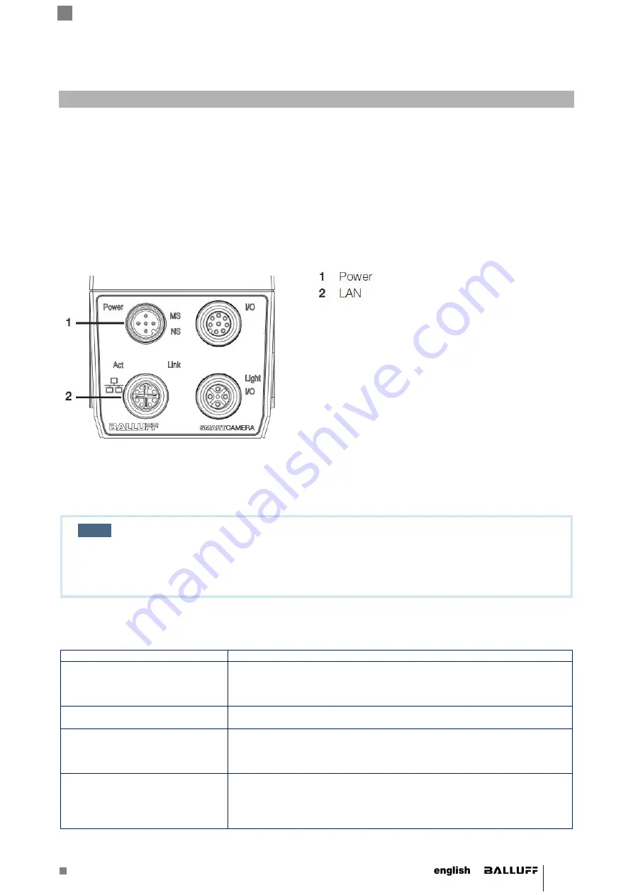
4.1 Step 1: Establishing a network connection with the SMARTCAMERA
Connect the
SMARTCAMERA
via the LAN port with the network.
Depending on the network topology between computer and
SMARTCAMERA
, different network settings must be made
on the computer.
In a company network or in a production facility, IP address are generally fixed.
NOTE
With
Release version 3.2
the BVS
SMARTCAMERA
Lite is shipped with the
fixed IP ad-
dress
192.168.10.2 (
Subnet mask
: 255.255.255.0).
For the firewall setting, Port 80 should be enabled.
The following network structures are possible:
Structure
Consequences
SMARTCAMERA
and PC are in
the same subnet of a local network
and no DHCP server is available
for automatic IP assignment.
In this case, the IP addresses of PC and
SMARTCAMERA
must be matched
and manually set. Pertinent useful notes are located in the section “Network
settings / LAN interfac
e”.
SMARTCAMERA
and PC are con-
nected directly via a LAN cable.
IP addresses are set automatically.
SMARTCAMERA
and PC are in
the same subnet of a local network
and a DHCP server is available for
automatic IP assignment.
IP addresses are set automatically.
SMARTCAMERA
and PC are in
different subnets of a local net-
work.
Subnets are explicitly created to be able to subdivide computers in different
networks and to structure it in this way. Since the different subnets, on the
other hand, are connected via switches, the communication with
the
SMARTCAMERA
is still possible. Pertinent useful notes are located in
the section “Network settings / LAN interface”.
Содержание BVS SC 1280Z00-07-000 Series
Страница 1: ...BVS SC _1280Z00 07 000 SMARTCAMERA IO...
Страница 2: ......
Страница 35: ...No EN 08 131532 G21 Subject to modification Replaces G20...


