Balluff Network Interface EtherCAT™
www.balluff.com
6
3
First steps
3.2.
Mechanical
connection
The module is secured by means of two M6 screws and two washers.
Insulation support is available separately.
3.3.
Electrical
connection
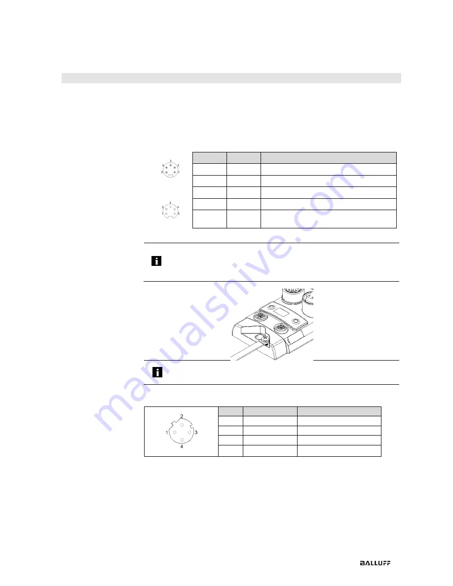
Power supply
IN
7/8”, male
OUT
7/8” female
Pin
Function
Description
1
0 V
GND Actuator supply
2
0 V
GND module / sensor supply
3
FE
Functional ground
4
+24 V
Module / sensor supply
5
+24 V
Actuator supply
Note
Where possible, establish sensor/bus power supply and actuator power supply
via a separate power supply.
Total current < 9 A The total current of all modules must not exceed 9A even in
the case of series connection of the actuator supply.
Grounding
Note
The ground connection between housing and machine must have a low
impedance and be as short as possible.
EtherCAT
interface
M12, D-coded, female
Pin
Function
Description
1
Tx+
Transmit Data +
2
Rx+
Receive Data +
3
Tx-
Transmit Data -
4
Rx-
Receive Data -


