background image

Instruction Manual

DCF-CO

69

Due to different granulometry and specific weights from the applied 

products, variations can be observed in relation to the presented table. 

We recommend performing the practical tests described in page 67 

before application.

  ATTENTION

The table was elaborated with 540 rpm in the PTO and transmission 

ratio (motor/moving).

 NOTE


ƒ

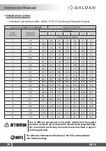
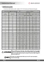
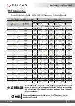
Distribution system

• Limestone distribution table - Kg/Ha - DCF-CO (Cardan and Hydraulic Engine)

Gears: Motor 

12 teeth

 Moving 

48 teeth

Rotation PTO 540 RPM

Scale

Opening

Amount of

Kg/Second

Wind speed

4 km/h

5 km/h

6 km/h

7 km/h

8 km/h

9 km/h

10 km/h

Amount of kg per Hectare

0

0,30

270

216

180

154

135

120

108

1

0,59

527

421

351

301

263

234

211

2

0,66

594

475

396

339

297

264

238

3

0,71

641

513

428

366

321

285

257

4

0,86

770

616

513

440

385

342

308

5

1,16

1046

837

698

598

523

465

419

6

1,24

1114

891

743

636

557

495

446

7

1,40

1256

1004

837

717

628

558

502

1,44

1296

1037

864

741

648

576

518

9

1,58

1424

1139

950

814

712

633

570

10

1,68

1512

1210

1008

864

756

672

605

11

1,82

1640

1312

1094

937

820

729

656

12

1,88

1688

1350

1125

964

844

750

675

13

1,97

1769

1415

1179

1011

884

786

707

14

2,17

1951

1561

1301

1115

975

867

780

15

2,34

2106

1685

1404

1203

1053

936

842

16

2,55

2295

1836

1530

1311

1148

1020

918

17

2,72

2450

1960

1634

1400

1225

1089

980

18

2,86

2572

2057

1715

1470

1286

1143

1029

19

3,08

2774

2219

1850

1585

1387

1233

1110

20

3,28

2950

2360

1967

1686

1475

1311

1180

21

3,44

3098

2479

2066

1770

1549

1377

1239

22

3,59

3233

2587

2156

1848

1617

1437

1293

Содержание DCF-CO

Страница 1: ...Lime Fertilizer and Organic Fertilizer Spreader DCF CO...

Страница 2: ......

Страница 3: ...ale was responsible for the custody and maintenance during the period in its possession and also for the assembly retightening lubrication and overhaul During the technical delivery dealer should guid...

Страница 4: ...Organic Fertilizer Spreader DCF CO BALDAN IMPLEMENTOS AGR COLAS S A CNPJ 52 311 347 0009 06 Insc Est 441 016 953 110 Scan the QR Code on the identification plate of your device and access this Instru...

Страница 5: ...Assembling the rubber deflector Optional 29 35 Assembling the hydraulic system DCF CO 3000 Hydraulic Engine 36 Assembling the hydraulic system DCF CO 6000 8000 Hydraulic Engine 37 UNLOCKING 38 Unlocki...

Страница 6: ...aulic Engine 73 MAINTENANCE 74 Tires pressure 74 Lubrification 75 Lubrification every 5 hours of work 76 Lubrification every 8 hours of work 77 79 Lubrification every 24 hours of work 80 Lubrification...

Страница 7: ...t to Technical Assistance and BALDAN company is authorized to carry the respective invoice in the name of the resale Any repairment carried in the product within the dealer warranty deadline will only...

Страница 8: ...ation Totheowner BALDAN IMPLEMENTOS AGR COLAS S A is not responsible for any damaged caused by accident duetousage transportation orintheimproperorincorrecttransportationofitsimplement whether by negl...

Страница 9: ...ottransportpeople on the tractor or over the equipment Do not work with the tractor if the front has insufficient ballast to the rear equipment Should there be a trend to lift add weights or ballasts...

Страница 10: ...DCF CO switch off the tractor first Use appropriate tools ATTENTION ATTENTION ATTENTION ATTENTION When transporting the DCF CO do not exceed the speed of 25Km h or 15 MPH in order to avoid risk of dam...

Страница 11: ...power switched off ATTENTION Do not climb or remain on the distributor discs under any circumstance Ignoring this warning maycausesevereaccidents ordeath Do not climb or stand on the conveyor under a...

Страница 12: ...ourself besides the tire never in front of it To inflate a tire always use a containment device inflation cage touching the head There is risk of injuries or death to the DCF CO operator and bystander...

Страница 13: ...DCF CO ATTENTION ATTENTION TheDCF COmayreleasefragmentsorthrowobjectsathighspeeds that can cause serious injury or death to bystanders ATTENTION Do not get exposed to the air coming out of rotating d...

Страница 14: ...ment PPE below IMPORTANT The safety practice must be performed in all stages of working with the DCF CO thus avoiding accidents such as impact of objects fall noise cuts and ergonomics ie the person r...

Страница 15: ...always trying to maintain the required stability In case of imbalance reduce acceleration turn the wheels to the slope side of the terrain and neverlifttheDCF CO Always drive the tractor at speeds co...

Страница 16: ...precautions so it is the owner s responsibility to implement safetyprocedureswhileworkingwiththeDCF CO Check the recommended minimum tractor power for each DCF CO model Only use the tractor wit powera...

Страница 17: ...t 2 Modulated Conveyor 3 Central Shaft 4 Central Cardan 5 Lateral Cardan 6 Hook Shackle 7 Support Bracket 8 Conveyor Turnbuckle 9 Framework 10 Tire 11 Transmission protection 12 Distributor discs 13 A...

Страница 18: ...ngine 1 Bucket 2 Modulated Conveyor 3 Deflector 4 Hook Shackle 5 Support Bracket 6 Conveyor Turnbuckle 7 Framework 8 Tire 9 Hydraulic Hose 10 Hydraulic engine 11 Transmission Protection 12 Distributor...

Страница 19: ...B mm Measurement C mm Measurement D mm DCF CO 3000 Cardan and Hydraulic Engine 1800 3900 582 1700 DCF CO 6000 Cardan and Hydraulic Engine 2000 4600 582 1800 DCF CO 8000 Cardan and Hydraulic Engine 200...

Страница 20: ...Simple 2 Tires 750x16 2 Tires 1070 50 70 DCF CO 6000 2 80 Tandem 4 Tires 750x16 4 Tires 1390 75 90 DCF CO 8000 3 80 Tandem 4 Tires 11L 15 4 Tires 1480 90 100 Approximate gauge 1600 mm PTO in RPM 540 R...

Страница 21: ...y may get caught in the DCF CO The DCF CO leaves factory semi assembled only requiring the assembly of its tires which were removed for easier loading and transportatin To assembly it follow the instr...

Страница 22: ...the screws 1 flat washers 2 pressure washers 3 and nuts 4 02 Then attachthedriverbox 5 totheDCF COandusethesamescrews 1 plainwashers 2 pressure washers 3 and nuts 4 for the central fixing of the drive...

Страница 23: ...04 Thenfastentheguideplates 11 totheguideplates 5 throughthescrews 12 plainwashers 13 lockwashers 14 andnuts 15 05 Finishbyreplacingthepin 16 flatwasher 17 andwingnut 18 5 To adjust the guide plates 1...

Страница 24: ...O 24 Assemblingthecanvasbaffle Optional PartI Deflector assemble the canvas baffle proceed as follows Assembly 01 Couple the central frame of the deflector 1 to the DCF CO attaching it with flat washe...

Страница 25: ...al PartII Assembly 02 Then attach the left side frame 4 to the central frame of the baffle 1 securing with pins 5 plain washers 6 and cotter pins 7 Repeat the procedure above to assembly the right sid...

Страница 26: ...as 8 overtheframes 9 passingtherods 10 insideholes A 9 8 10 10 A A 12 10 13 14 11 04 Then fasten the rods 10 in the DCF CO using the shaft 11 lock 12 pressure washers 13 and nut 14 12 10 13 14 11 Asse...

Страница 27: ...themtotheframes 9 throughthescrews 16 pressure washers 17 and nuts 18 06 Then fastentherods 15 intheDCF CO usingtheshaft 16 lock 17 pressurewashers 18 andnuts 19 15 15 B B 16 16 18 17 18 9 15 15 17 9...

Страница 28: ...InstructionManual DCF CO 28 07 Finishbyplacingthespacers 20 onthebarinsidethecanvas 8 20 20 8 Assemblingthecanvasbaffle Optional PartV Assembly...

Страница 29: ...and nuts 4 1 2 4 3 Before beginning the rubber baffle assembly procedure optional make sure that the DCF CO is engaged to the tractor Ignoring this warning will make the DCF CO tip causing damage to t...

Страница 30: ...e the central guard of the baffle 5 into the DCF CO attaching it with screws 6 flat washers 7 pressure washers 8 and nuts 9 10 03 Then fasten the central frame of the baffle 5 on the rear support 10 t...

Страница 31: ...ing plate 15 in the central frame of the baffle 5 using screws 16 flat washers 17 pressure washers 18 and nuts 19 Assemblingtherubberbaffle Optional PartIII Assembly 16 15 5 19 18 17 NOTE The cover pl...

Страница 32: ...n the central frame of the baffle 5 using support bars 21 bearing 22 screws 23 plain washers 24 pressure washers 25 and nuts 26 Finish the assembly by attaching the support bracket 27 20 5 21 27 23 22...

Страница 33: ...e central frame of the baffle 5 securing it with screws 29 bushing 30 pressure washers 31 and nuts 32 5 28 29 31 30 32 Assemblingtherubberbaffle Optional PartV Assembly Repeat the procedure above to a...

Страница 34: ...and upper rubber guards on the right side frame NOTE 07 Theattachthesiderubberguard 33 ontheleftside frame 28 usingbars 34 screws 35 lockwashers 36 andnuts 37 08 The place the upper rubber guard 38 on...

Страница 35: ...CO usingtheshaft 46 aflatwasher 47 alock 48 washer 49 and nut 50 48 47 51 49 50 43 28 46 45 44 52 NOTE When fixing the adjuster 43 on the side frame its length must be adjusted through the rods 51 and...

Страница 36: ...ngine 2 and attach the nipple 3 and the hydraulic hose 4 of the PACKAGING HOSE OF 1 2 X 4700 MM W 1 TRG AND 1 TRF W QUICK COUPLING MALE HOSE HYDR HIGH PRESSURE OF 1 2 X 500 MM W 1TCG AND 1TRG SAE 100...

Страница 37: ...lic engine 2 and attach the nipple 3 and hydraulic hose 4 of the PACKAGING HOSE OF 1 2 X 5400 MM W 1 TRG AND 1 TRF W QUICK COUPLING MALE HOSE HYDR HIGH PRESSURE OF 1 2 X 500 MM W 1TCG AND 1TRG SAE 100...

Страница 38: ...e assembly unlock the wheel support 1 before work or transport and proceed as follows Unlockingthewheelsetpin 01 Loosen the pin 2 and remove the pin 3 3 2 1 Do not work or transport the DCF CO 6000 an...

Страница 39: ...serving the following item 01 Levelthecouplinghead 1 oftheDCF COwiththetractor scouplingthroughtheadjuster 2 02 Then slowly approach the tractor to the DCF CO in reverse paying attention when to use t...

Страница 40: ...ecouplinghead 1 oftheDCF COwiththetractor scouplingthroughtheadjuster 2 02 Then slowly approach the tractor to the DCF CO in reverse paying attention when to use the brakes 03 Then couple the DCF CO h...

Страница 41: ...transportation work position by proceeding as follows 01 Remove the support bracket 1 from point A and place it on B Hitch Supportbracket DonotortransporttheDCF COwiththesupportbracket 1 atpoint A Ig...

Страница 42: ...02 Then levelthedistributor watchingthelongitudinallevelling length inrelationtotheground fromtheside 03 Otherwise level it through the tractor s drawbar using the height that results in the best DCF...

Страница 43: ...the TDP and the other in the DCF CO Then steer the tractor until one of its rear tires approaches the DCF CO Place the cardan parts side by side and check for a minimum clearance of 5 to 7 cm between...

Страница 44: ...in the same length as the protective tubes Shortentheinnerandouterguardsofthe cardan proportionally Remove all burrs and edges Clean and grease the cardan bars Before coupling the cardan check the le...

Страница 45: ...or observing that the engagement will only be completed when lock 1 springs out FULL HITCH 1 3 2 3 RIGHT ASSEMBLY CLEAR ANCE MISALIGNED INNER FORKS WRONG ASSEMBLY The contact surface between the pipe...

Страница 46: ...hedoffwiththeparkingbrake applied This speed s function is feeding the discs for a uniform distribution The DCF CO Cardan is shipped with a 16 48 gear combination for other combinations proceed as fol...

Страница 47: ...16 Teeth 48 Teeth 2 16 Teeth 16 Teeth 3 16 Teeth 12 Teeth 4 12 Teeth 48 Teeth 5 12 Teeth 16 Teeth 03 Then remove the chain 6 loosen the retaining ring 7 remove the gear 8 release the ring lock 9 and r...

Страница 48: ...ing the discs for a uniform distribution The DCF CO Hydraulic Engine is shipped with a 16 48 gear combination for the other combinations proceed as follows 01 Loose the nut 1 lock washer 2 flat washer...

Страница 49: ...8 Dentes 2 16 Dentes 16 Dentes 3 16 Dentes 12 Dentes 4 12 Dentes 48 Dentes 5 12 Dentes 16 Dentes 17 12 16 13 14 15 18 19 04 Then removethechain 12 loosentheretainingring 13 removethegear 14 releasethe...

Страница 50: ...is accompanied by a tachometer 1 The tachometer 1 is used to calibrate the RPM of the hydraulic engine Before the RPM calibration proceedasfollows CalibrationRPM HydraulicEngine PartI 1 5 01 Loosen t...

Страница 51: ...measure the RPM If the result is not 540 RPM adjust the RPM on the tractor and redo the measurement to the recommended 540 RPM for the work 03 Then cut the sticker 6 at the size of 1 cm and glue it t...

Страница 52: ...04 If there is greater clearance adjust the belt tension 1 for this loosen the locknut 2 the nuts and locknuts 3 and adjust the tensioner 4 When adjustment is complete retighten the nuts and locknuts...

Страница 53: ...hrough the tensioner 2 To adjust chain 1 tension proceed as follows 01 Loosen the nut 3 slide the tensioner 2 by adjusting the chain tension 1 02 Then retighten the screw 3 securing the tensioner 2 1...

Страница 54: ...h the inner nut 4 of the tensioner 5 02 Thenadjustbelttension 1 throughtheouternut 6 ofthetensioner 5 andthenretighten the inner nut 4 and the nut 2 of the pulley 3 The allowed clearance is 3 5 cm IMP...

Страница 55: ...wer part of the bel 5 onto the B pulley from the right distributor disc 03 Then twist the belt 5 and thread it into the C pulley of the left distributor disc 04 Finally pass the belt 5 through the D p...

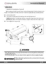
Страница 56: ...just the product flow proceed as follows Adjustments Shut offgateadjustment 01 Loosenthewingnut 3 02 Thenpullthelever 4 adjustingtheopeningorclosingofthegate 1 accordingtothegraduated scale 2 from 0to...

Страница 57: ...ts Positionoffinsinthedistributordiscs POSITION A POSITION B POSITION C Ifitisrequiredtochangetheprocedureforapartoftheproductforbetterdistributionuniformity only 3finsmaybeadjustedatdifferentanglesfr...

Страница 58: ...lly important component for the user s personal safety and for the cardan shaft s lifespan Adjustments Cardanrecommendations 35 15 15 35 INASHORTPERIODOFTIME INCONTINUOUSWORK Do not work with the DCF...

Страница 59: ...working requirement 3 1 2 2 03 Then retighten the wing nuts 3 LOWER guide plates The limestone fertilizer or organic compound jet has shorter reach HIGHER guide plates The limestone fertilizer or orga...

Страница 60: ...rting the works with DCF CO check if its baffle 1 is properly secured tightening the washers and nuts 2 preventing the baffle 1 from coming off damaging the conveyor and the DCF CO Operations Usingthe...

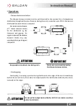
Страница 61: ...mpensate for the distribution deficiency tha occurs naturally at the edges Operations Distancebetweenstrokes Overlapping Do not perform adjustments while the DCF CO is in motion or with an active tran...

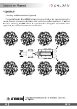
Страница 62: ...rough the distribution discs delivering a uniform application throughout the area Optionally the DCF CO can be acquired with a driving box for in line fertilizer application for example under the base...

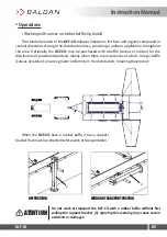
Страница 63: ...oducts mainly when there are occurences of winds Using a baffle canvas or rubber ensures greater uniformity in the distribution retaining the product When the DCF CO have a rubber baffe it has a suppo...

Страница 64: ...ON 01 Remove the locks 1 flat washers 2 and uncouple the regulator 3 from the trolley 4 02 Then lift the side frames 5 couple the adjuster 3 tothecentralframe 6 andfixitthroughplainwashers 7 andlock 8...

Страница 65: ...esponding rotation on the engine in the tractor manual This traction engine rotation changes from tractor to tractor 10 Always observe the operation of the limestone distributing mechanisms and the se...

Страница 66: ...er Sales Telephone 0800 152577 E mail posvenda baldan com br 20 To engage or uncouple the cardan the TDP must be switched off 21 The weight of the product is related to its granulometry and density 22...

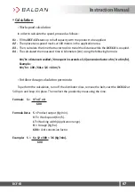
Страница 67: ...onfactorofm stoKm hr Example Km hr 100 60s x 3 6 6 Km h S Product output Kg min VT Work speed Km h LT Working width Application range D Dosage Kg ha 600 Unit conversion factor 01 Fill the DCF CO s tan...

Страница 68: ...1 14 1026 821 684 586 513 456 410 5 1 55 1395 1116 930 797 698 620 558 6 1 65 1485 1188 990 849 743 660 594 7 1 86 1674 1339 1116 957 837 744 670 8 1 92 1728 1382 1152 987 864 768 691 9 2 11 1899 1519...

Страница 69: ...527 421 351 301 263 234 211 2 0 66 594 475 396 339 297 264 238 3 0 71 641 513 428 366 321 285 257 4 0 86 770 616 513 440 385 342 308 5 1 16 1046 837 698 598 523 465 419 6 1 24 1114 891 743 636 557 49...

Страница 70: ...709 10 5 04 4536 3629 3024 2592 2268 2016 1814 11 5 47 4921 3937 3281 2812 2460 2187 1968 12 5 63 5063 4050 3375 2893 2531 2250 2025 13 5 90 5306 4244 3537 3032 2653 2358 2122 14 6 50 5852 4682 3902 3...

Страница 71: ...79 10 6 72 6048 4838 4032 3456 3024 2688 2419 11 7 29 6561 5249 4374 3749 3281 2916 2624 12 7 50 6750 5400 4500 3857 3375 3000 2700 13 7 86 7074 5659 4716 4042 3537 3144 2830 14 8 67 7803 6242 5202 44...

Страница 72: ...8 96 8064 6451 5376 4608 4032 3584 3226 11 9 72 8748 6998 5832 4999 4374 3888 3499 12 10 00 9000 7200 6000 5143 4500 4000 3600 13 10 48 9432 7546 6288 5390 4716 4192 3773 14 11 56 10404 8323 6936 5945...

Страница 73: ...78 1022 852 730 639 568 511 11 1 540 1386 1109 924 792 693 616 554 12 1 660 1494 1195 996 854 747 664 598 13 1 780 1602 1282 1068 915 801 712 641 14 1 900 1710 1368 1140 977 855 760 684 15 2 020 1818...

Страница 74: ...tire position yourself besides the tire never in front of it To inflate a tire always use a containment device inflationcage Assemble the tires with proper equipment The service should only be perform...

Страница 75: ...egarding its efficiency and purity avoiding products contaminated by water dust and other agents Tableofgreasesandequivalents For equivalent manufacturers and or brands that are not listed in the tabl...

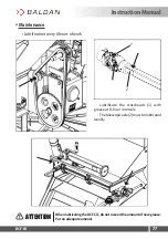
Страница 76: ...InstructionManual DCF CO 76 Maintenance Lubrificationevery5hoursofwork When lubricating the DCF CO do not exceed the amount of new grease Put an adequate amount ATTENTION...

Страница 77: ...Lubrificationevery8hoursofwork Lubrificate the crossheads 1 with grease at 8 hour intervals Thetelescopicaxle 2 mustbelubricated weekly 2 1 When lubricating the DCF CO do not exceed the amount of new...

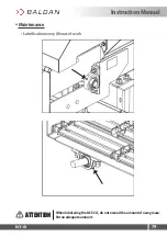
Страница 78: ...InstructionManual DCF CO 78 Maintenance Lubrificationevery8hoursofwork When lubricating the DCF CO do not exceed the amount of new grease Put an adequate amount ATTENTION...

Страница 79: ...InstructionManual DCF CO 79 Maintenance Lubrificationevery8hoursofwork When lubricating the DCF CO do not exceed the amount of new grease Put an adequate amount ATTENTION...

Страница 80: ...InstructionManual DCF CO 80 Maintenance Lubrificationevery24hoursofwork When lubricating the DCF CO do not exceed the amount of new grease Put an adequate amount ATTENTION...

Страница 81: ...structionManual DCF CO 81 Lubrificationevery30hoursofwork Maintenance Lubrificationevery60hoursofwork When lubricating the DCF CO do not exceed the amount of new grease Put an adequate amount ATTENTIO...

Страница 82: ...is not too compacted on the conveyor wich may occur with dry powder products 03 When adjusting the belt tensioner one side may be tighter than the other Only use factory original fuses since they are...

Страница 83: ...fill with the breather cap 3 until oil leaks through the level vent 2 03 Finish by placing level indicator screw 2 and breather plug 3 back again Do not fill with oil above the level Only use the spec...

Страница 84: ...couple the cardan 3 from the shaft 4 Before starting the reduction gearbox change make sure that the tractor is turned off DO NOT replace reduction gearbox if tractor is on Ignoring this warning may c...

Страница 85: ...en loosen the cotter pin 14 and remove the fuse pin 15 to loosen the flanges 16 Maintenance DCF CO Cardan reductiongearboxreplacement PartII 13 12 11 11 14 15 16 03 Then loosen the handles 11 open the...

Страница 86: ...ews 17 lock washers 18 and nuts 19 06 Then loosen the screws 20 lock washers 21 nuts 22 and remove the bracket 23 07 Then loosen the screws 24 lock washers 25 nuts 26 and remove the reduction gearbox...

Страница 87: ...ent PartIV 22 23 21 17 19 20 18 29 25 24 26 10 The couple the new reduction gearbox 29 securing it through the screws 24 lock washers 25 and nuts 26 11 Then couple the bracket 23 securing it through t...

Страница 88: ...Maintenance DCF CO Cardan reductiongearboxreplacement PartV 14 15 16 13 12 11 11 12 Then lock the flanges 16 trhough the fuse pin 15 and the cotter pin 14 13 Then couple the belt 13 close the lid 12...

Страница 89: ...efore commencing work perform a general overhaul and ensure that all components are correctly assembled ATTENTION 14 Then couple the chain 10 and couple the protective cover 9 securing it through the...

Страница 90: ...arbox if tractor is on Ignoring this warning may cause serious injury or death ATTENTION 01 Loosen the screws 1 lock washers 2 flat washers 3 and remove the plate 4 02 Then release the hydraulic hoses...

Страница 91: ...placement PartII 18 19 20 20 21 23 19 18 22 21 27 24 25 26 05 Then release the wing nuts 18 lock washers 19 flat washers 20 screws 21 remove the protective cover 22 and the chain 23 06 Then release th...

Страница 92: ...ce DCF CO HydraulicMotor reductiongearboxreplacement PartIII 30 29 28 28 31 32 33 07 Then loosen the handles 28 open the cover 29 and loosen the belt 30 08 Then loosen the cotter pin 31 and remove the...

Страница 93: ...screws 34 lock washers 35 and nuts 36 10 Then loosen the screws 37 lock washers 38 nuts 39 and remove the bracket 40 11 Then loosen the screws 41 lock washers 42 nuts 43 and remove the reduction gear...

Страница 94: ...gearboxreplacement PartV 46 42 41 43 39 40 38 34 36 37 35 14 Then couple the new reduction gearbox 46 securing it through the screws 41 lock washers 42 and nuts 43 15 Then couple the braket 40 securin...

Страница 95: ...ntenance DCF CO HydraulicMotor reductiongearboxreplacement PartVI 31 32 33 30 29 28 16 Then lock the flanges 33 through the fuse pin 32 and the cotter pin 31 17 Then couple the belt 30 close the lid 2...

Страница 96: ...rtVII 27 24 25 26 18 19 20 20 21 23 19 18 22 21 18 Then couple the mounting bracket 27 securing through the screws 24 lock washers 25 and flat washers 26 19 The couple the chain 23 and the protective...

Страница 97: ...ATTENTION 4 1 2 3 10 11 13 14 15 12 16 6 7 17 9 5 8 20 Then couple the bushing 17 securing through the screw 16 lock washer 15 and nut 14 21 Then engage the hydraulic motor 13 securing it through the...

Страница 98: ...ochangethecrownshaftandwormgearpinion remove the reduction gearbox from the DCF CO as instructed on pages 84 to 89 for DCF CO Cardan and pages 90 to 97 for DCF CO Hydraulic Motor Then drain all reduct...

Страница 99: ...2 8 9 10 10 10 8 9 OLD OLD NEW NEW 10 11 12 10 10 Maintenance Crownandpinionreplacement Reductiongearbox PartII 04 Then removetheoldbearings 10 fromtheoldcrownshaft 8 andthewormgearpinion 9 06 Then at...

Страница 100: ...ructed on pages 55 and 56 ATTENTION 2 3 14 4 1 2 When the reduction gearbox assembly 2 is finished if the smaller cover 5 and large cap 1 have gaps replace the paper gaskets 13 and 14 IMPORTANT 07 The...

Страница 101: ...wer distribution discs Check the position of the fins if they are not inverted according to the rotating direction of the distributor discs If they are inverted proceed with their correct assembly Rot...

Страница 102: ...ardan assembly or worn out crosshead Assemble the cardan or replace crossheads with excessive wear Loosen or damaged bearings Retighten the bearings or replace them if damaged Conveyor adjustment Tens...

Страница 103: ...CF CO IMPORTANT Generalcleaning 01 When storing the DCF CO perform a general cleaning and wash it thoroughly with water only Make sure the paint has not worn out if this has happened apply a general c...

Страница 104: ...at the end of the work season 02 Use neutral products to clean the distributor following the safety and handling guidelines provided by the manufacturer 03 Always carry out maintenance during the per...

Страница 105: ...te all chains and greases according to the recommendations in the operator s manual 09 Spray the whole machine especially zinc parts with protective oil following the manufacturer s application instru...

Страница 106: ...check that your tractor meets the requirements for hydraulic engine operation HYDRAULIC ENGINE SYSTEM For the operation of the hydraulic engine system and the DCF CO with hydraulic engine the tractor...

Страница 107: ...ories PartII The driver box is used for jobs where the application of the fertilizer should be directed in line for exampleundercanopies For work on clay soils the DCF CO 3000 and 6000 can be optional...

Страница 108: ...tionalaccessories PartIII The baffle with canvas is used for the distribution of powdered products mainly when there are occurrences of winds Using the baffle ensures greater distribution uniformity r...

Страница 109: ...ptionalaccessories PartIV The baffle with rubber is used for the distribution of powdered products mainly when there are occurrences of winds Using the baffle ensures greater distribution uniformity r...

Страница 110: ...rial number 2 and manufacturing date 3 which is on the nameplate of your DCF CO The drawings in this Instruction Manual are merely illustrative ATTENTION In case of doubts never operate or handle your...

Страница 111: ...__ State _________________________________________________________________ Certificate of Warranty no _______________________________________________ Implement ________________________________________...

Страница 112: ...InstructionManual DCF CO 112 Notes...

Страница 113: ...InstructionManual DCF CO 113 Notes...

Страница 114: ...ecallouttoTechnical Assistance and Baldan company is authorized to carry the respective invoice in the name of the resale Any repair carried in the product within the dealer warranty deadline will onl...

Страница 115: ...s ___________________________ Number ___________________________ City __________________________________________ State __________________ E mail _______________________________________________________...

Страница 116: ......

Страница 117: ...___________________________ Number ___________________________ City __________________________________________ State __________________ E mail ________________________________________________________...

Страница 118: ......

Страница 119: ..._______ Number ___________________________ City __________________________________________ State __________________ E mail _______________________________________________________________ Sale date ___...

Страница 120: ...HE STAMP WILL BE PAID BY BALDAN IMPLEMENTOS AGR COLAS S A Av Baldan 1500 NovaMat o CEP 15993 900 Mat o SP Brasil Tel 16 3221 6500 Fax 16 3382 6500 www baldan com br email sac baldan com br Export Tel...

Страница 121: ......

Страница 122: ......

Отзывы: