Bakers Pride Cyclone CO11-E1 Скачать руководство пользователя страница 5

2. Field Connections

a. Remove access panel from the right side of the oven.
b. Feed  power  cable  (supplied  by  the  customer)  through  the  access  hole  in  the  rear  of 

the  oven  and  pull  the  cable  to  the  front  of  the  oven  under  the  access  panel  where  it 
may be attached to the cable support bracket.

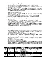
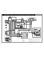
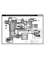
c. Following  the  appropriate  wiring  diagram  conforming  to  the  rating  plate,  connect  the 

power  supply  leads  to  the  field  wiring  terminal  block.  The  ground  wire  should  be 
connected to the grounding lug attached to the cable support bracket.

d. Make sure all connections are tight, and replace the access cover.

5

5. INITIAL START-UP

After installation, your oven will need approximately 1 hour to burn off. The following steps must be 
completed before your new oven is ready for use:

a. Place the oven in a well ventilated area as the following procedure may produce smoke and 

fumes.

b. Open the door(s) and remove any instructions or samples shipped with the unit. Make sure 

the oven cavity is empty and the wire shelves are properly installed.

c. Close the oven door(s) and set the temperature knob to 300°F (150°C) for ½ hour.
d. After  ½  hour,  increase  the  temperature  to  500°F  (260°C)  for  at  least  ½  hour  more.  This 

procedure will dry out the insulation and will help to insure best baking results.


!

!

CAUTION: 

Overexposure to smoke or fumes may cause nausea and dizziness. 

Be sure the oven is placed in a well ventilated area

.

6.  SYSTEM CHECK: ROTARY CONTROL

a. Open the oven door(s).
b. Turn selector switch to high. The green indicator light near the selector switch and oven light(s) 

will illuminate.

c. Close the door(s). Oven light(s) will go off and fan will run. Make sure fan is rotating clockwise 

looking from front.

d. Press oven light switch. Oven light(s) will go on and go off as the switch is released.
e. Turn the thermostat knob. The amber indicator light near the thermostat will illuminate and the 

elements will come on.

f.

Turn the timer knob and set a time of 2 minutes. At the end of 2 minutes, you will hear the buzzer. 
Turn the timer knob to “0”.

g. Open the oven door(s). Oven light(s) will go on, and elements and fan will go off.
h. With the door(s) open turn the selector switch to “Cool Down” position. The fan will run to cool 

down the oven.

i.

Turn selector switch to “0” position.

j.

Close the oven door(s).

Motor / Blower

Speeds

208V and 220-240V (60hz)

400-Y (50hz)

High = 1725 RPM

High = 1425 RPM

Low = 1140 RPM

Low = 950 RPM

!

!

IMPORTANT:

 The oven will begin to heat as soon as the door(s) is/are closed, if 

the oven temperature is lower than the temperature set and the selector switch 
is in the “High” or “Low” cook position.

The thermostat indicator light will turn on and stay on while the oven is heating 
up, and will turn off when the set temperature has been reached.

The door(s) interlock switch will deactivate the motor and heating elements and 
turn on the light when the door(s) is/are opened.

Содержание Cyclone CO11-E1

Страница 1: ...alteration service or maintenance can cause property damage injury or death Read the Installation Operating and Maintenance Instructions thoroughly before installing or servicing this equipment FOR YO...

Страница 2: ...2 d COC E CO11 E 230 400V CE w FAST Temperature Controller E 6 13 6 Parts Lists w Exploded Views 14 a CO11 E 14 b COC E 17 7 Warranty 20 2 INSTALLATION INSTRUCTIONS 1 RECEIVING Read the notice on the...

Страница 3: ...ed mounted to unit The legs are packed inside the unit with the wire shelves b After unpacking the unit remove legs and any other material from inside the oven c Place the unit on a counter or other f...

Страница 4: ...there is any strain on the power supply cable 4 ELECTRICAL CONNECTIONS 1 General Instructions a Alicensed electrician must make electrical connections b When installed unit must be electrically groun...

Страница 5: ...sea and dizziness Be sure the oven is placed in a well ventilated area 6 SYSTEM CHECK ROTARYCONTROL a Open the oven door s b Turn selector switch to high The green indicator light near the selector sw...

Страница 6: ...a Close the oven door s b Turn selector switch to High or Low position The green indicator light near the selector switch will be illuminated c Turn the thermostat knob to the desired cooking tempera...

Страница 7: ...ers Pride Software for Cyclone Series Convection Ovens supplied with this option e Load the oven with the product to be cooked f Turn the timer knob to the desired bake time and timer will begin count...

Страница 8: ...or product residue from stainless steel use ordinary soap and water with or without detergent applied with a sponge or cloth Dry thoroughly with a clean cloth Never use vinegar or corrosive cleaner D...

Страница 9: ...uld only be performed by a factory authorized technician 7 Call the factory toll free number 800 431 2745 for the name of an authorized service location in your area 8 Replacement parts manual sent wi...

Страница 10: ...LEMENTS AMBER PILOT LIGHT THERMOSTAT 250V LIGHTS 28 BRN 28 BRN 26 WHT 27 WHT 25 BRN 24 BLK 23 BLK 7 WHT 8 BRN 4 BRN 5 BLK 16 WHT A1 H1 H2 STEAM OPTION A2 WHT A1 BLK 29 BLK 31 BLK H2 H1 POTENTIOMETER T...

Страница 11: ...WIRES NOTES SENSOR WHT RED GC20 3006 HEATING ELEMENTS AMBER PILOT LIGHT THERMOSTAT 250V LIGHTS 28 BRN 28 BRN 26 BLK 27 WHT 25 BLU 24 BLU 23 BLU 7 BRN 8 WHT 4 BLK 5 BLU 16 BRN A1 H1 H2 STEAM OPTION A2...

Страница 12: ...EAT INDICATOR SINGLE PHASE TB1 X E Y Z TERMINAL BLOCK 2 L1 L2 TIMER L2 PRESENT ONCO11 ONLY STEAM SWITCH TIMER POTENTIOMETER TIMER STEAM OPTION BLU RED YEL BLK WATER SOLENOID VALVE 4 1 5 2 3 6 LIGHT SW...

Страница 13: ...2 S1 13 C2 14 15 A5 C2 7 S1 13 4 34 32 31 16 18 S2 A6 H6 15 ROTARY SWITCH 15 33 1 2 3 POWER INDICATOR HEAT INDICATOR SINGLE PHASE TB1 X E Y Z TERMINAL BLOCK 2 L1 L2 TIMER L2 PRESENT ONCO11 ONLY STEAM...

Страница 14: ...E D R P I E D w S r i o tc o h D w S r i o tc o h D 1 2 3 4 5 6 7 8 9 10 11 12 13 14 15 16 17 18 19 20 21 22 23 24 25 26 27 28 29 30 31 32 33 34 35 36 37 40 44 43 41 38 39 42 45 46 47 48 50 49 51 52...

Страница 15: ...affle Plate 68 M1176X Potentiometer 23 Q2009A Thumb Screw 1 4 20x1 2 4 69 M1335X Bell Audiolarm 24 E3095X Baffle Plate Bracket Assy 4 70 S1311X Knob 3 25 Q1414A Screw Hex Hd 10x3 4 8 71 M1352X P1166A...

Страница 16: ...oller Chain 35 Chain Connection Link 41 Turnbuckle 1 4 20x3 1 4 20 Hex Nut Left Hand Thread 2 30 Leg Set of 4 Leg Bolt Set For 4 Legs 24 1 2 S S Leg Set 4 Used w Casters 24 1 2 S S Leg each Used w Cas...

Страница 17: ...Dn ow Dn Up Up e c S e t l e c S e t l nu Men u Me ar St t ar St t t S op t S op ow Dn ow Dn He at g in He at g in t S ea m t S ea m 2 2 2 3 1 4 5 6 7 8 9 10 11 12 13 14 12 13 14 15 16 17 18 19 21 20...

Страница 18: ...er 10 18 T3042A Rack Support 2 61 Q1402A Nut 10 32 12 19 K1088K Horizontal Seal Strip 2 62 S1062X Terminal Cap 6 20 K1089K Vertical Seal Strip 2 63 Q1408X Nut 10 24 6 21 S6037X Door Gasket 64 Q1436A B...

Страница 19: ...2 22 E3210U Contactor Bracket 6 M1217X Motor 1 4HP 2 Spd 200 230V 50 60 23 E1018K Terminal Box 7 Q3014A Lockwasher Split 5 16 4 24 Q1407A Bolt Hx Hd 10x1 2 2 8 Q2204A Nut HX 5 16 18 4 25 E1176K Cable...

Страница 20: ...riod of THREE MONTHS The installation of these replacement decks is the responsibility of the purchaser The extended Cyclone door warranty years 3 through 5 is a parts only warranty and does not inclu...

Отзывы: