Consolidated 1511 Series Safety Valve Instruction Manual
| 17
© 2020 Baker Hughes Company. All rights reserved.
E. Spindle Runout
It is important that the spindle be kept very straight in
order to transmit the spring force to the disc without lateral
binding. Overgagging is one of the common causes of
bent spindles. A method to check the essential working
surfaces of the spindle is illustrated in Figure 6.
Using a spindle check stand (see Figure 6 as a
reference), place the ball end of the spindle into a
depression at the base “B” of the stand. Lean the upper
portion of the spindle against the “V” block. It should be
touching the spindle just below the threads on the upper
portion of the spindle. Using a machinists indicator on a
45° angle at spindle shoulder "C", rotate the spindle and
read the Total Indicator Run out on the indicator. If the
T.I.R is less than values shown in Table 2, the spindle may
be returned to service. If the T.I.R is greater than these
values, straighten the spindle using "V" blocks and a
hydraulic press until the T.I.R is found to be acceptable.
Other parts of the spindle not used as working surfaces
may run out considerably more than .007” (0.18 mm), but
this should not be regarded as unacceptable. Although
the upper thread end is not a working surface, excessive
bending in this area could affect the accuracy of the
Consolidated Hydroset device, and/or the Consolidated
Electronic Valve Tester (
EVT
™), if either of these devices is
used to verify valve set pressure.
F. Spring and Spring Washers
Spring wire that is irregularly spaced, or the ends are
not parallel, are sufficient causes for replacement. The
spring washers are machined to fit the ends of the
spring - there should be no more than a .030” (0.76 mm)
clearance between the spring and the spring washer. If
a spring is badly damaged by corrosion (flaking, pitting,
or reduction in wire diameter), replace the spring with
the proper spring. If the spring is unable to be identified
contact your local Green Tag Center.
G. Lift Restrictor
On 1511 valves with set pressures of 26 psig (1.79 barg)
and below will have a Lift Restrictor installed on the
spindle stem, located inside the spring. Measure to verify
minimum length for the appropriate orifice as per Table 3.
If under the minimum length, replace the Lift Restrictor.
XI. Maintenance Instructions (Cont’d)
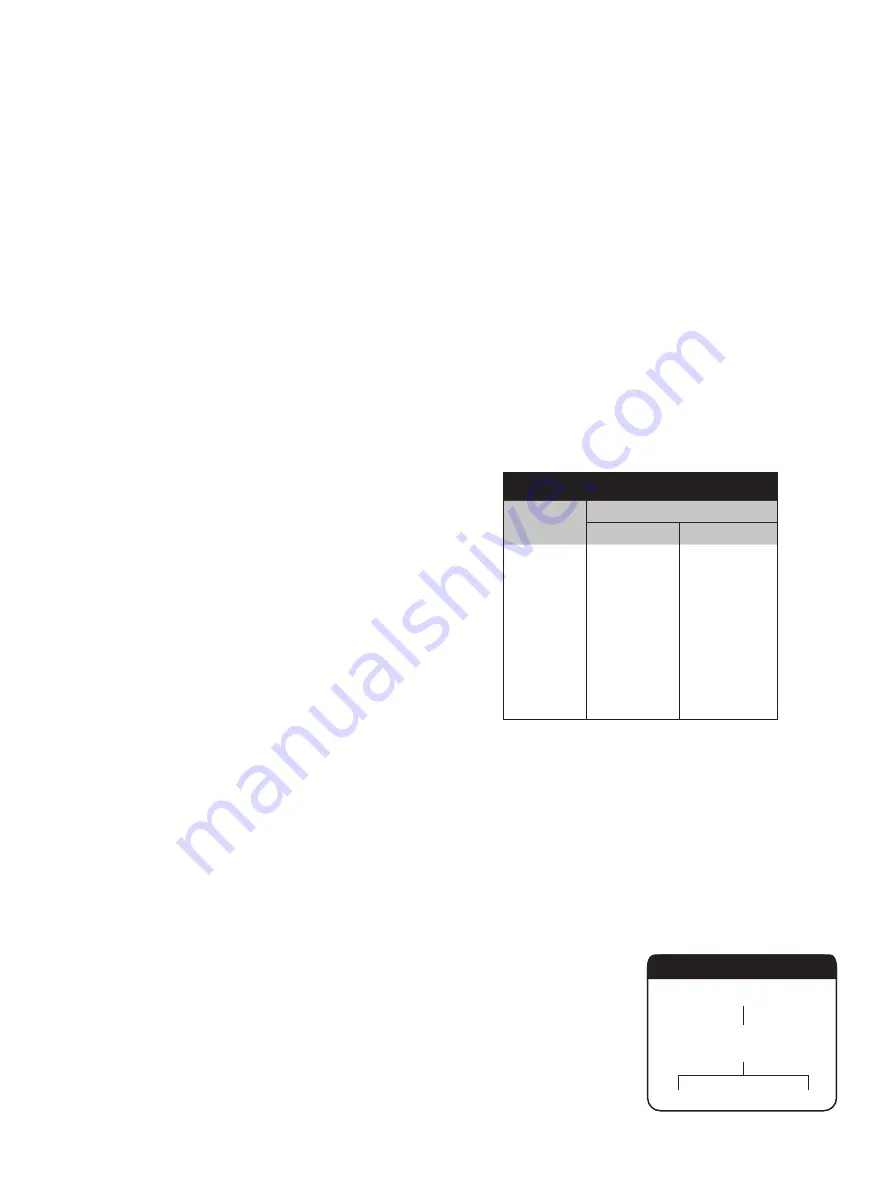
Table 3: Lower Pressure Lift Stop
Orifice
L min
in.
mm
H
2.25
57.0
J
2.25
57.0
K
3.50
88.8
L
3.50
88.8
M
3.50
88.9
N
3.50
88.9
P
3.94
100.0
Q
5.00
127.0
A. General Information
Once the valve is disassembled, the appropriate parts can be inspected for damage and
their suitability for reuse.
B. Specific Steps
1. Inspect the guide inside diameter for egging, and ensure the inside surface is
smooth. The threads on the outside must be in good condition to ensure the
adjusting ring/guide will adjust when the valve is hot. If serious, large scale galling
or ridges corresponding to the grooves in the disc are present, the part should be
replaced.
2.
Disc :
The 1511 Safety Valve is designed with a Flat Solid Disc (FSD) in either a low
pressure (LP) or high pressure (HP) version (Refer to Table 4).
Disc
1511
FSD
(LP)
(HP)
Table 4
XII. Inspection and Part Replacement


