COMPONENT DESCRIPTION AND REPLACEMENT
MULTIBUS MODULES
WBPEEUI220760A0
6 - 7
IIMRM02 Multibus Reset Module
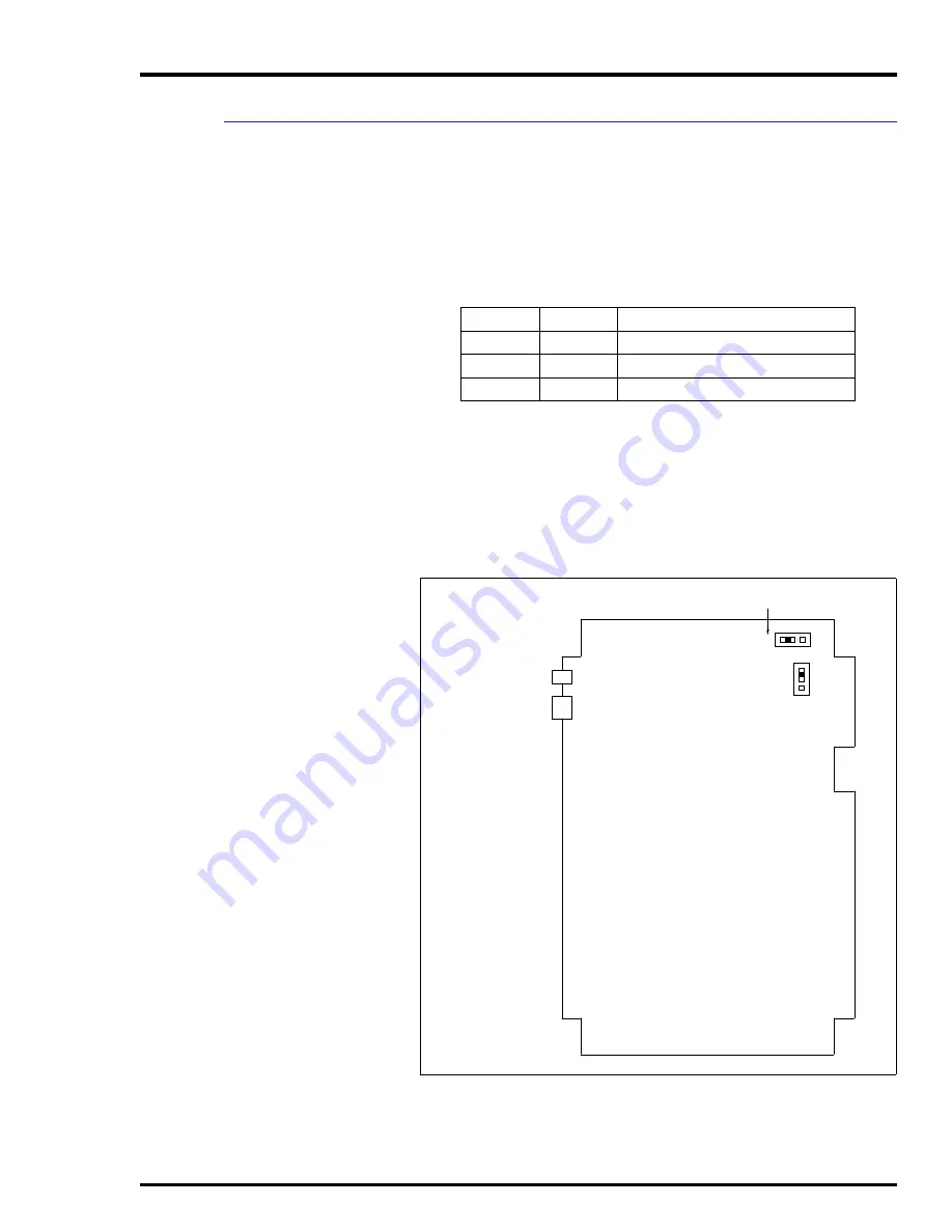
This module replaces the IIMKM02A module when the driver
cabinet is used. The reset module provides power fault inter-
rupt and a reset signal to the multibus backplane. Refer to Fig-
ure
for jumper location. Refer to Table
for jumper
settings.
Jumper J4 on the MRM module enables or disables the out of
tolerance voltage detection of the power supply. Default is to
disable detection.
Jumper J5 on the MRM module changes polarity of the out of
tolerance signal from the power supply. Leave jumper J5 in the
default position (pin two to pin three).
Table 6-6. IIMRM02 Jumper Settings
Jumper
Setting
Description
J4
1-2
Disable OOT voltage detection
2-3
Enable OOT voltage detection
J5
2-3
Factory setting - no selection
Figure 6-4. IIMRM02 Multibus Reset Module
TO PFI ON
POWER SUPPLY
OUT OF TOLERANCE
(OOT) JUMPER
TO RESET SWITCH
ON POWER ENTRY
PANEL
P4
P3
J4
J5
1
1
2
2
3
3
TP35489D


