background image

COMPONENT DESCRIPTION AND REPLACEMENT

FAN ASSEMBLY FOR THE MULTIBUS CARD CAGE

6 - 4


WBPEEUI220760A0 

®

2. Follow the procedure under 

MULTIBUS CARD CAGE

 and

remove the cage. 

3. Cut and remove cable ties securing the fan assembly power
cord. 

4. Remove the two long screws on either side of the fan
assembly and slide the fan assembly out around the multibus
card cage.

NOTES:
1.

Be sure the arrow on the fan being installed points in the direc-

tion of the air flow.

2.

Be sure the red striped conductor of the power cord is con-

nected to the + (positive) terminal of the fan.

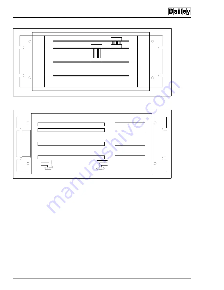
Figure 6-1.  Multibus Card Cage (Front View)

Figure 6-2.  IIOIS43 Multibus Card Cage (Rear View)

IIMCP01
IIMCP02

IIMLM01

IIMCL01

IIMRM02
IIMKM02A

TP36283C

TP36141B

P5

P6

FAN

+5

+12

COM

-12

+5

+12

COM

-12

Содержание 40 Series

Страница 1: ... Process Control and Automation Solutions from Elsag Bailey Group IIOIS43 Operator Interface Station 40 Series Hardware Manual ...

Страница 2: ...MENTS ÉLECTRONIQUES SONT SENSIBLES AUX PERTURBATIONS PAR FRÉQUENCE RADIO DES PRÉCAUTIONS DEVRONT ÊTRE PRISES LORS DE L UTILISATION DU MATÉ RIEL DE COMMUNICATION PORTATIF LA PRUDENCE EXIGE QUE LES PRÉCAUTIONS À PRENDRE DANS CE CAS SOIENT SIGNALÉES AUX ENDROITS VOULUS DANS VOTRE USINE PERTURBATIONS DU PROCÉDÉ L ENTRETIEN DOIT ÊTRE ASSURÉ PAR UNE PERSONNE QUALIFIÉE EN CONSIDÉRANT L ASPECT SÉCURITAIRE...

Страница 3: ...e console and INFI 90 OPEN system to familiarize the reader It then explains the operations that can be performed after config uring the console Configuration Gives the procedures to configure the con sole as a system for proper operation with its peripherals and the INFI 90 OPEN system It also explains each func tion of the console and gives configuration procedures and requirements This instruct...

Страница 4: ...l 6 1 through 6 33 Original 7 1 through 7 3 Original A 1 through A 12 Original B 1 through B 3 Original Index 1 through Index 3 Original When an update is received insert the latest changed pages and dispose of the super seded pages NOTE On an update page the changed text or table is indicated by a vertical bar in the outer mar gin of the page adjacent to the changed area A changed figure is indic...

Страница 5: ... com pressed air injury to the eyes could result from splashing solvent as it is blown off the printed circuit board p 5 3 Replace the fuse with one of the same type and rating Using an improper fuse could lead to injury to personnel and equipment dam age from fire or electrical shock p 6 14 6 25 The monitor will slide out the rear of the cabinet by itself when the mounting bolts are removed The m...

Страница 6: ...DRE GÉNÉRAL Environnement de l équipement Ne pas soumettre les composants à une atmosphère corrosive lors du transport de l entreposage ou l utilisation Possibilité de chocs électriques durant l entretien Débrancher l alimentation ou prendre les précautions pour éviter tout contact avec des composants sous tension durant l entretien AVERTISSEMENTS D ORDRE SPÉCIFIQUE Assurez vous que tous les couve...

Страница 7: ... de tension sur les périphériques le bloc d alimentation et le panneau d entrée des alimentations correspondent bien à la ten sion de service Une tension incorrecte risque d endommager l equipment Assures vous que le disjoncteur d alimentation princi pal de la console est étient avant de modifier les réglages de ten sion de service afin d éviter d endommager l équipment p 3 24 6 32 Coupez l alimen...

Страница 8: ...ON 3 7 AC POWER WIRING GUIDELINES 3 8 AC OUTLETS 3 9 WIRING CONNECTIONS AND CABLING 3 10 MONITOR INSTALLATION 3 16 OPERATOR INTERFACE DEVICES 3 17 Operator Keyboard 3 17 IIAKB03A Engineering Keyboard 3 17 IIATB05 Trackball and IIAMS04A Mouse 3 18 IIADP01 Annunciator Display Panel 3 19 IIADP02 Annunciator Display Panel 3 19 Touch Screen 3 21 CONTROLLER CARD INSTALLATION 3 21 TOUCH SCREEN INSTALLATI...

Страница 9: ...ecking Connections 5 3 Cleaning the Monitor 5 4 Cleaning the Operator Keyboard 5 4 Cleaning the Engineering Keyboard 5 4 Cleaning the Printed Circuit Boards 5 4 GENERAL CLEANING AND WASHING 5 4 CLEANING EDGE CONNECTOR 5 5 CLEANING FEMALE EDGE CONNECTORS 5 5 Cleaning the Floppy Disk Drive Head 5 6 Cleaning the DAT Tape Drive Head 5 6 Checking Power Supply Outputs 5 6 Checking and Inspecting Power E...

Страница 10: ...embly 6 23 Replacing Fuses 6 26 Floppy Disk Drive 6 26 Color Monitor 6 26 CPU 6 28 Console and Driver Cabinet 6 28 Graphics Card Settings 6 30 Hard Drive Settings 6 31 CD ROM Drive Settings 6 32 DATA STORAGE DEVICES 6 32 IIDOP05A OPTICAL DISK 6 32 PERIPHERALS 6 33 SECTION 7 SUPPORT SERVICES 7 1 INTRODUCTION 7 1 REPLACEMENT PARTS AND ORDERING INSTRUCTIONS 7 1 TRAINING 7 1 TECHNICAL DOCUMENTATION 7 ...

Страница 11: ...32 3 22 IIVTE0 Video Diagnostics and Start Up Terminal 3 38 3 23 Standard Ethernet Thinwire for Isolated Network Console 3 39 3 24 Standard Thinwire to Plant Wide Thickwire Network 3 39 3 25 Alternative Thinwire Connection to Plant Wide Thickwire Network 3 40 3 26 Alternative Ethernet Thickwire Configuration 3 41 3 27 Alternative Console Thickwire to Plant Wide Thickwire 3 41 3 28 Alternative Conc...

Страница 12: ... Drive Settings A 10 A 14 CPU Motherboard SW 4 Switch Setting to OFF for HALT Operation A 11 A 15 CPU Graphics Board Settings A 11 A 16 Floppy Drive SCSI Address Setting A 12 B 1 Redundant OIS Configuration B 2 B 2 Redundant OIS Driver Cabinet Configuration B 2 B 3 Redundant Ethernet Configuration B 3 List of Tables No Title Page 1 1 IIOIS43 Models 1 2 1 2 Glossary of Terms and Abbreviations 1 5 1...

Страница 13: ...ntive Maintenance Schedule 5 2 6 1 CPU Applications 6 1 6 2 Hardware 6 1 6 3 SCSI Bus Hardware Addresses 6 2 6 4 Multibus Card Cage Modules 6 3 6 5 IIMKM02A Jumper Settings 6 6 6 6 IIMRM02 Jumper Settings 6 7 6 7 IIMLM01 Dipswitch Settings 6 9 6 8 IIMCP01 Switch Settings 6 11 6 9 IIMCP02 Factory Default Jumper Settings 6 12 6 10 IIMCP02 Communications Processor Configuration 6 13 6 11 DC Distribut...

Страница 14: ...ude AlphaStation Trademark of DEC Digital Equipment Corporation INFI 90 Registered trademark of Elsag Bailey Process Automation INFI NET Registered trademark of Elsag Bailey Process Automation Plant Loop Registered trademark of Elsag Bailey Process Automation Velcro Trademark of Velcro U S A Incorporated ...

Страница 15: ... interface station OIS INTENDED USER System engineers and technicians with a background in pro cess control systems should read this instruction thoroughly before installing and using the system Do not put the console into operation until you read and thoroughly understand this instruction This instruction is a reference for installers with installation and maintenance experience on process contro...

Страница 16: ...ngs for air intake to cool the inside of the cabinet The console cabinet has a stabilizer which must be fastened to the front of the cabinet when the console is not secured to the floor A 63 5 millimeter Table 1 1 IIOIS43 Models Model Description IIOIS43X1 Console with lower monitor IIOIS43X2 Console with upper monitor IIOIS43X3 Console with upper and lower monitor IIOIS43XA Driver cabinet with on...

Страница 17: ... bottom of the driver cabinet The driver cabinet contains the power entry panel with power supply CPU and multibus card cage There is no annunciator display panel or keyboard interface panel in the driver cabinet z Figure 1 2 Driver Cabinet Front View IIOIS43XD CPUs MULTIBUS CARD CAGE MULTIBUS CARD CAGE POWER ENTRY PANEL POWER ENTRY PANEL TP80639A FRONT VIEW FLOPPY DISK DRIVE FLOPPY DISK DRIVE OPT...

Страница 18: ...ation on software faults Maintenance Contains a schedule and procedures for maintenance Component Description and Replacement Describes how to replace hardware and the printed circuit boards in the multibus card cage Support Services Includes a spare parts list and ordering instructions Quick Reference Information Contains jumper switch and fuse locations for quick refer ence Redundant Ethernet Ne...

Страница 19: ...op controller with data acquisition and information processing capabilities OIS Operator interface station Integrated operator console with data acquisition and reporting capabilities providing a digital access into the process for flexible control and monitoring PEP Power entry panel PFI Power fail interrupt A signal that causes active controller or processor modules MFCs or MFPs to reset and the...

Страница 20: ...ole mount lower monitor and keyboard IIOIS43X2 Operator interface station integrated unit with monitor upper with tilt swivel base and keyboard IIOIS43X3 Operator interface station integrated unit with dual moni tors one console mount and one tilt swivel base mount and keyboard IIOIS43XA Driver cabinet style operator interface station with one set of electronics IIOIS43XD Driver cabinet style oper...

Страница 21: ...tes Monitor resolution 1280 x 1024 pixels at 72 Hz refresh 0 28 dot pitch DAF 52 transmissivity Monitors supported Two monitors The DEC AlphaStation 255 model 233 outputs eight win dows The windows can be sent to a main console and any number of auxil iary consoles Model Voltage Typical Amps Maximum Amps Typical Watts Maximum Watts IIOIS43X1 120 2 93 3 78 250 335 240 1 54 2 08 250 335 IIOIS43X2 12...

Страница 22: ...c tape optical disk Maximum trend storage Three months refer to the Configuration Operator Interface Station 40 Series IIOIS43 instruction Configuration Nonvolatile ROM and hard disk memory Environment Temperature Relative humidity Altitude Operating 10 to 40 C 50 to 104 F Storage 20 to 60 C 4 to 140 F Operating 20 to 80 noncondensing Recommended minimum 40 Storage 10 to 90 noncondensing 0 3 to 2 ...

Страница 23: ...IONS SUBJECT TO CHANGE WITHOUT NOTICE Table 1 5 IIOIS43 Console Specifications continued Property Characteristic Value Model Height Width Depth cm in cm in cm in IIOIS43X1 107 27 42 23 71 12 28 00 109 01 42 92 IIOIS43X2 156 94 61 78 71 12 28 00 109 01 42 92 IIOIS43X3 156 94 61 78 71 12 28 00 109 01 42 92 IIOIS43XA 221 28 87 12 60 96 24 00 76 20 30 00 IIOIS43XD 221 28 87 12 60 96 24 00 76 20 30 00 ...

Страница 24: ...s allowing data to be condensed in each display Any graphic ele ment can be mixed with any symbol on any display such as schematics faceplates trends and alarm summaries For OIS operating procedures refer to the Operation instruction Table 1 3 Figure 2 1 is a block diagram of the communication process Figure 2 1 Communication Levels IIOIC251 IIOIC252 IIOIC253 IIOIC254 IIOIC255 IIOIC421 IIOIC422 II...

Страница 25: ...em process data and communication data by interfacing it to an INFI NET or Plant Loop system Three cards in the multi bus card cage make up the interface unit They are the IIMCL01 Multibus Communication Loop Termination Module Figure 2 2 Block Diagram MOUSE TRACKBALL KEYBOARD INTERFACE PANEL IIMKM02A KEYBOARD MODULE MOUSE TRACKBALL NIU IIMCL01 COMMUNICATION LOOP MODULE INFI NET IIMLM01 LOOP MODULE...

Страница 26: ...KM module to the keyboard connector on the CPU The IIMRM02 reset module for driver cabinets used in place of IMKM02A provides module bus reset and is located in slot four The CPU in the OIS console may control up to two monitors on the OIS console Monitor cable s plug into the connectors on the back of the monitor The CPU also allows communications with the printers on the ethernet network cable T...

Страница 27: ... with static sensitive devices The kit is designed to connect the techni cian and the static dissipating work surface to the same ground point to prevent damage to the static sensitive devices by electro static discharge Use the static grounding wrist strap when installing and removing modules Static discharge may damage static sensi tive devices on modules in the cabinet Use grounded equip ment a...

Страница 28: ...led the shipment 4 Use the original packing material or container to store the console 5 Store the console in a place with clean air free of extremes of temperature and humidity Refer to Section 1 for the console specifications Do not remove or install circuit boards with power applied to the console The circuit board may be damaged Remove power to all AC wiring when removing or connecting AC wire...

Страница 29: ...ement of modules in the multibus card cage Refer to MULTIBUS CARD CAGE in Section 6 to compare the module placement and to check the switch settings 5 Connect the Plant Loop or INFI NET communication high way either coaxial or twinaxial cable to the multibus commu nication loop module IIMCL01 The REMOTE LOCAL switch on the board selects the power source for the board The switch is factory set to L...

Страница 30: ...u bleshooting information CONSOLE CABINET INSTALLATION Before the OIS console cabinet is set into place in a control room insure that the floor is level in the area where the cabi nets will be set Make sure the location can accommodate the console Figure 3 1 shows the console cabinet and anchoring dimensions Figure 3 1 OIS Console and Anchoring Dimensions TP80605B 711 2 28 00 1085 7 42 75 1568 3 6...

Страница 31: ...move the top up to 6 35 millimeters 0 25 inches up down forward or back toward the cabinet to line up the table top 4 Two steel table alignment pins are shipped inside the brass bushings located on each side of each tabletop When two tabletops are lined up push the pins outward into the bushing of the table to the right of the cabinet Tighten the three bolts on each tabletop support bracket Figure...

Страница 32: ...e Dimensions TP35319B IICPI01 482 6 19 00 335 3 13 20 52 8 2 08 69 3 2 73 50 8 2 00 404 1 15 91 493 8 19 44 DIMENSIONS MILLIMETERS INCHES 493 8 19 44 50 8 2 00 493 8 19 44 TP35320B 615 4 24 23 254 5 10 02 956 6 37 66 395 7 15 58 482 6 19 00 1089 7 42 90 IICPI02 DIMENSIONS MILLIMETERS INCHES 482 6 19 00 791 5 31 16 885 2 34 85 ...

Страница 33: ...evice in the driver cabinet Before the driver cabinet is set into place ensure that the floor is level in the area where the cabinet will be set The unit must be secured to the floor before it is wired or operated The cabi net dimensions are shown in Figure 3 5 The dimensions for locating the mounting screws are shown in Figure 3 6 Figure 3 5 Driver Cabinet Dimensions ONE DOOR OPEN COOLING AIR ENT...

Страница 34: ...e power entry panel has alarm relay outputs located on a terminal block and cable con nectors for peripheral devices Note that the alarm relay out puts are for alarm annunciation only Figure 3 6 Driver Cabinet Anchoring Dimensions NOTES 1 FOR O PTIONAL W ELD MO U NTIN G W ELD BO TTO M OF CABINET BASE TO IM BED DED STEEL FIVE PLAC ES FRO NT AND BAC K STAR TIN G AT EAC H CO RNER AND EQUALLY SPACED W...

Страница 35: ... the power wiring and must be bare green colored or green yellow colored if insulated The grounding conductor must be terminated at the system safety ground connection on the front of the power entry panel Over current protection provided for the AC distribution must be sized to allow for the inrush current required by the OIS hardware Refer to specifications in Section 1 for peak inrush current a...

Страница 36: ...cage Refer to Figure 3 7 for IIMCL01 module location of communi cation loop cable connectors Peripheral devices connect to the front of the power entry panel Refer to PERIPHERALS for spe cific instructions on installing and configuring peripheral devices Figure 3 7 IIMCL01 Module Communication Loop Connections TWINAXIAL CONNECTIONS TO IIMLM01 P3 TWINAXIAL CONNECTIONS TB2 F1 REMOTE LOCAL J7 F2 P7 I...

Страница 37: ... terminal location for OIS43 driver cabinets Refer to Figure 3 9 for AC input terminal location for OIS43 consoles Table 3 1 Wiring Color Codes Color Function Brown AC hot inside PEP chassis only Blue AC neutral Green Yellow Protective earth ground Brown 5 VDC White Green DC common Violet 12 VDC White Violet 12 VDC Green Remote voltage sense signal wire White Remote voltage sense signal wire Figur...

Страница 38: ...sts a description of the cable connections shown in Figures 3 10 and 3 11 Figure 3 9 Console Power Entry Panel U DEGAUSS REAR VIEW NOTICE CONNECT POWER CORD BEFORE CONNECTING SIGNAL CABLE 2 NO POWER MAIN POWER ON OFF WARNING AVERTISSEMENT 120 240V PERIPHERAL POWER UPPER CRT POWER SUPPLY LOWER CRT BLOWER AUX NOTICE CONNECT PERIPHERAL RIBBON CABLE BEFORE PLU GGING AND POWERING UNIT E1 ON ON WRISTSTR...

Страница 39: ... RS 232 C PORT 1 VGA P1 P2 ANNUNCIATOR DISPLAY PANEL ADP DC POWER FAN P6 CONTRAST BRIGHTNESS POWER VGA MONITOR 2 BEZEL CONTRAST BRIGHTNESS TB1 P4 P5 P6 P7 TB2 LOOP 1 LOOP 1 LOOP 1 LOOP 2 LOOP 2 LOOP 2 P3 TERM STRIP AC POWER IN AC POWER OUT BEZEL AC IN CUSTOMER SUPPLIED AC POWER P10 P5 P2 P2 P1 P6 P5 P6 P2 E1 P7 P5 TERM BLOCK MONITOR MONITOR MONITOR 1 FLOPPY DISK DRIVE AND CONTROLLER 28 30 27 22 33...

Страница 40: ...l P10 on keyboard interface board Mouse port on CPU through adapter 9 6634512 26N4 Internal I O P3 on IIMCL01 P3 on IIMLM01 10 6634512 26N4 Internal I O P4 on IIMCP01 02 P4 on IIMLM01 P7 P4 P3 P8 TERM STRIP DC DIST BOARD BACKPLANE PEP P3 P4 P3 P1 J1 RESET PERIPHERAL P4 P4 P3 IIMLM01 LOOP MODULE DEGAUSS L DEGAUSS U CPU J3 J2 POWER SUPPLY MOUSE KEYBOARD SCSI DC POWER TB1 P4 P5 P6 P7 TB2 LOOP 1 LOOP ...

Страница 41: ...tribution board P5 on backplane 21 6640368 1 DC Power P6 on DC distribution board P6 on backplane 22 6640369 1 DC Power P2 on power supply Terminal strip on DC distribution board 23 6640371 1 AC power J1 on power entry panel P1 on power supply 24 6640640 1 DC Power P7 on DC distribution board Cable P2 to fan on card cage Cable P3 to fan on back door 25 6640640 3 DC Power P8 on DC distribution boar...

Страница 42: ...nection panel and two are located on the power entry panel Monitor wiring connector location may be slightly different for each OIS console NOTE The monitor is autosensing and does not need to be switched if the power to the cabinet is 120 or 240 VAC However if other monitors are used they may need to be switched to prevent damage from over or under voltage Figure 3 12 identifies the color monitor...

Страница 43: ...ter is supplied with the keyboard All consoles have a five pin DIN connector on the keyboard interface panel Plug in the keyboard at the AUX KBD connector Power does not have to be removed from the console before plugging in or unplugging the keyboard Initializing the system is not needed after plugging in or unplugging the keyboard If necessary key board mapping information is in the Operation in...

Страница 44: ...R BACK FORW D DISPLAY SUMM MISC MENU PREV PAGE NEXT PAGE GROUP GRAPHIC HELP DETAILS OP PARAMS CANCEL TUNE DISPLAY SWITCH AREA 3 AREA 11 AREA 4 AREA 12 AREA 5 AREA 13 AREA 6 AREA 14 AREA 7 AREA 15 ACK ALARM PAGE ACK SILENCE AREA 8 AREA 16 Z TP35387A ENTER ESC CLEAR F17 Help Do Ctrl F1 Hold F3 Set Up F6 Inter Halt F8 Cancel F7 Resume F9 Main Screen F10 Exit F11 Alt Char F18 PrtSc F19 Scroll Lock PF4...

Страница 45: ...ple ADPs IIADP02 Annunciator Display Panel The IIADP02 annunciator display panel provides an additional 32 LEDs and pushbuttons Each LED is assigned to a tag Each pushbutton may be assigned to a display or a key macro When a tag goes into an alarm condition the assigned LED turns on Press the pushbutton to call the display or key macro assigned to it Refer to Figure 3 17 for the address dipswitch ...

Страница 46: ...P PANEL ADDRESS SWITCH PC BOARD ADDRESS SWITCH SETTINGS SW1 1 2 3 4 5 6 7 8 1 2 3 4 5 6 7 8 1 2 3 4 5 6 7 8 1 2 3 4 5 6 7 8 OPEN OPEN OPEN OPEN SW1 SW1 SW1 ADP 1 ADP 2 ADP 3 ADP 4 P1 SW1 1948978 1 P1 P2 P2 P2 ADP 2 ADP 3 ADP 4 1 2 3 4 5 6 7 8 OPEN BACK OF ADP PANEL ADDRESS SWITCH PC BOARD 8 7 6 5 4 3 2 1 8 7 6 5 4 3 2 1 OPEN SW1 SW1 ADP 1 ADDRESS SWITCH SETTINGS TO MKM BOARD 26 PIN TP35495C P2 P4 ...

Страница 47: ...igure 3 19 shows the dipswitch settings and jumper positions of the touch screen controller card and the jumpers on the IIMKM02A board Before attaching the touch screen ribbon cable to the controller board ground the capacitive charge on the touch screen to the monitor case ground 1 Insert one end of a 24 AWG wire into either outside touch screen cable connector contact 2 Press the other end of th...

Страница 48: ...ine calibration can be done from the console For operating information refer to the Operation and Configuration instructions Table 1 3 TOUCH SCREEN JUMPER SETTINGS Jumpers J6 through J9 on the IIMKM02A keyboard module control the touch screen accessory Fig 3 19 1 For OIS consoles with upper or lower monitors set jumpers J6 and J8 at 1 to 2 2 For OIS consoles with dual monitors set jumpers J6 throu...

Страница 49: ...P6 P7 P8 P9 P18 P14 W3 W4 W2 W1 P15 CONNECTOR PINS PLUG INTO MKM BOARD FACTORY SET DO NOT CHANGE NOT USED TOUCH SCREEN CABLE MOUNTING HOLES 4 W1 INSTALLED W2 NOT INSTALLED P15 J5 J4 IIMKM02A FOR TOUCH SCREEN R3 1 5 S1 S2 P16 J3 1 2 3 1 2 3 3 2 1 S1 8 7 6 5 4 3 2 1 S2 4 3 2 1 CLOSED ON CLOSED ON J9 1 2 3 1 2 3 J7 1 2 3 J6 1 2 3 J8 P17 P14 J2 J1 ...

Страница 50: ... show the correct operating voltage Equipment damage may result if the incorrect voltage is connected Make sure the con sole main power circuit breaker is off before changing operat ing voltage setting or equipment damage may result Remove power from all peripheral equipment and the console before installing or removing peripheral equipment Equipment damage may result ATTENTION Assurez vous que to...

Страница 51: ... sequence must be completed for the software to recognize a printer Refer to the File Utili ties instruction Table 1 3 for that sequence Table 3 6 lists the printer cable part numbers and cable lengths Table 3 7 lists the printers used by the serial interface 3 IIMCP02 module 4 CD ROM 5 DAT tape drive 6 Optical disk drive 7 CPU Table 3 5 SCSI Bus Hardware Addresses continued Address SCSI Bus Devic...

Страница 52: ...inter through the menu and connecting cables Connect the power and commu nication cables at the back of the printer Connect the power cable into a local AC outlet For more information refer to the manufacturer s documentation NOTE Step 1 applies only to IIPRT02 IIPRT03 IIPRT05 and IIPRT09 printers For cabling information on the IIPRT08B IIPRT08C and IIPRT10 printers refer to Figure 3 21 and the ap...

Страница 53: ... 20 IIPRT02 IIPRT03 IIPRT05 IIPRT09 TP36103B Table 3 8 IIPRT02 Printer Setup Values Item Control Description Setting The present configuration is Firmware 512621 Resolution MED Printhead 18P 1 Font Style 507339 DP 400 CPS 2 144 CPI 10 Country USA Mode Normal 2 LPI Lines per inch 6 LPI 3 Forms control inches Form length 11 0 Top margin 0 0 Bottom margin 0 0 4 Interface control Interface type Serial...

Страница 54: ...e 3 8 IIPRT02 Printer Setup Values continued Item Control Description Setting Table 3 9 IIPRT03 Printer Setup Values Item Control Description Setting The present configuration is Firmware 512623 Resolution MED Printhead 18P 1 Font Style 507339 DP 400 CPS 2 144 CPI 10 Country USA Mode Normal Ribbon type Process 4 color 2 LPI Lines per inch 6 LPI 3 Forms control Form length 11 0 Top margin 0 0 Botto...

Страница 55: ...Description Setting Table 3 10 IIPRT05 Printer Setup Values Item Control Description Setting The present configuration is Firmware 44A513152 SY 44A5131531M 1 Font Style 44A513153 Data Processing CPI 12 0 Country USA Mode Normal Horizontal expansion X1 Vertical expansion X1 2 LPI Lines per inch 6 LPI 3 Forms control in Form length 11 0 Form is 007 Offset from top of form 0 0 Top margin 0 0 Bottom m...

Страница 56: ...n the following list Table 3 11 do not match those of the IIPRT09 printer when checked select the data to be changed and make the appropriate corrections Fol low the manufacturer s instructions for changing setup values 6 Horizontal tabs columns None 7 Vertical tab stops in Default 8 Printer control straps Printer straps A 0 1 2 3 12345678901234567890123456789012 00000000000000000011000001001010 P...

Страница 57: ... Skip over perforation No Page length in 11 Cut sheet Line spacing 6 LPT Page length 11 Paper transparency Paper Symbol sets Character set Set I Code page USA Language set American Zero character Slashed General interface Max receive buffer SK Print suppress effective Yes Auto feed XT Epson Valid CPU compensation Standard Serial interface Parity None Serial data 7 8 bits 8 Protocol X ON X OFF Diag...

Страница 58: ...s This printer offers both color and black and white printing Note that the black and white is monochrome and not gray scale The printer will print a full size window display from the OIS console on a single page CX JetSeries CutSheet Paper is rec ommended for color copies A good quality photocopier paper should be used for black and white copies HP glossy media and HP transparency media require a...

Страница 59: ...0 color printer LaserJet IIISI compatible with PCL5 The last digit of the nomenclature determines the operating voltage of the printer 1 120 VAC 2 220 VAC Use the buttons and indicators on the control panel to operate the printer For more information refer to the manufacturer s documentation 1 Load the print media 2 Press the power switch The READY indicator lights 3 It prints on English A and B a...

Страница 60: ...nd writes to digital audio tape The tape drive has two SCSI ports The other port is for another SCSI device or terminator Related products for the tape drive are listed in Table 3 12 When power is turned on to the tape drive and no cassette is in the drive the tape and activity and write protect indicators light for approximately one to five seconds This indicates that the power on self test is ru...

Страница 61: ...pment damage may result Plug in the tape drive cable and verify that the supply voltage requirement of the tape drive matches the power supplied by the power entry panel before turning on the tape drive Equip ment damage may result A notice on the front of the power entry panel states the operating voltage Never connect the tape drive to the CPU with the CPU or tape drive power on Failure to compl...

Страница 62: ... archiving units are available The console uses the tabletop IIDOP04A optical disk The driver cabinet uses the rack mounted IIDOP05A optical disk If an additional IIDOP05A is required order part number 1949017 1 and 1947950 2 power cord to receive the optical disk unit with out duplicate mounting brackets and hardware The RWZ52 optical disk drive is a SCSI compatible storage device that reads and ...

Страница 63: ... one Set the operation mode to 0 NOTE If the operation mode is changed it will be necessary to power cycle the optical disk drive so that the drive recognizes the new mode It may also be necessary to reboot the host system Read the instruction manual shipped with the unit It contains important installation connection and troubleshooting infor mation IIVTE0 Video Terminal When using a driver cabine...

Страница 64: ...his instruction for more information ETHERNET CONFIGURATIONS Follow these ethernet configuration rules closely to correctly set up the network An ethernet message can pass through up to two repeaters or network bridges before it reaches its destination Ethernet networks require a terminator at each end of the cable The figures in this section are guidelines Each network may require changes due to ...

Страница 65: ... PORT STANDARD ETHERNET THINWIRE CABLE TP21048E TOTAL THINWIRE CABLE LENGTH TERMINATOR TO TERMINATOR CAN BE 185 M 607 FT MAX TERMINATOR THINWIRE PORT THINWIRE PORT THINWIRE TRANSCEIVER TRANSCEIVER TO THINWIRE ADAPTER 1948778A2 STANDARD ETHERNET THINWIRE CABLE STANDARD ETHERNET TRANSCEIVER CABLE TOTAL THINWIRE CABLE LENGTH TERMINATOR TO TERMINATOR CAN BE 185 M 607 FT MAX TOTAL THICKWIRE CABLE LENGT...

Страница 66: ...hickwire can be used to connect various pieces of an OIS system Figure 3 26 shows an alternative example thickwire network Figure 3 27 shows thickwire connections to a plant wide thickwire network Figure 3 25 Alternative Thinwire Connection to Plant Wide Thickwire Network STANDARD ETHERNET TRANSCEIVER CABLE CONSOLE THINWIRE NETWORK CONSOLE THINWIRE NETWORK NETW ORK BRIDGE STANDARD ETHERNET TRANSCE...

Страница 67: ... PORT OIS CONSOLE THICKWIRE TRANSCEIVER TRANSCEIVER PORT TRANSCEIVER PORT STANDARD ETHERNET TRANSCEIVER CABLE STANDARD ETHERNET TRANSCEIVER CABLE CABLES TO PRINTERS AND VT TYPE TERMINALS STANDARD ETHERNET THICKWIRE CABLE TERMINATOR THINWIRE PORT STANDARD ETHERNET TRANSCEIVER CABLE NETW ORK BRID G E STANDARD ETHERNET TRANSCEIVER CABLE TP21055A PLANTWIDE THICKW IRE NETWORK PLANTWIDE THICKWIRE NETWOR...

Страница 68: ...and all auxiliary consoles are installed and powered up install the software and configure the system Refer to the File Utilities instruction Table 1 3 for software loading boot parameters and setting the SCSI speed Refer to the Operation instruction Table 1 3 for complete operating information Refer to the Configuration instruction for com plete configuration information Table 1 3 SYSTEM OPERATIO...

Страница 69: ... panel resets the modules in the multibus card cage and the keyboard for INFI 90 keyboard and network interface unit Use the mul tibus reset if the keyboard does not respond If SW 4 on the CPU motherboard is set to OFF Fig 3 31 the reset button on the front of the CPU will become a HALT but ton Use the CPU HALT switch if the console does not respond NOTE Pressing the HALT switch on the CPU halts t...

Страница 70: ...uit boards containing MOS devices into antistatic bags when stored or shipped back to the factory Do not repair printed circuit boards in the field All repairs and adjustments should be performed by qualified personnel TROUBLESHOOTING The general troubleshooting guide in Table 4 1 may help to identify problems and suggest solutions WARNING There are exposed AC and DC connections inside the cabinet...

Страница 71: ...ed with the consoles are marked UPPER CRT LOWER CRT BLOWER AUX POWER SUPPLY The fifth AC outlet is located on the front on the power entry panel and is marked PERIPHERAL POWER 4 The line voltage should be 90 to 132 VAC RMS for a 120 VAC input and 180 to 264 VAC for a 240 VAC input Refer to the Site Planning and Preparation instruction Table 1 3 for specific AC voltages Start up OK but no network i...

Страница 72: ...ing from the multibus card cage 2 Unplug DC power distribution cables from all peripheral devices disk drives disk drive controller module and ADP panel Disconnect the power cables at the distribution side of the cables NOTE Turn power off before removing or inserting multibus mod ules 3 Unplug all multibus modules from the card cage The mod ules do not have to be pulled all the way out Pull them ...

Страница 73: ...0 0 0 1 0 1 1 1 0 0 1 0 n n n n Loop failure check for break in circuit MLM module loop back test failure Internal software error 31 32 33 0 0 1 1 0 0 0 1 0 0 1 1 0 0 1 0 0 0 1 1 0 0 1 1 Memory or CPU failure Address or bus error Illegal instruction 35 36 38 0 0 1 1 0 1 0 1 0 0 1 1 0 1 1 0 0 0 1 1 1 0 0 0 Spurious exception Divide by 0 check format error MLM module not configured for MCP module op...

Страница 74: ...t handshake failure Table 4 3 IIMLM01 Module Failure LED Code continued MLM Module Code LED Number Top Bottom 1 2 3 4 5 6 7 8 Error Condition Table 4 4 NNIU01 Network Interface Unit Error Codes Decimal Error Code Error Description 0 No error 1 Waiting for loop 2 Improper format 3 Illegal command 4 Index already established 5 Block already established at another index Loop PCU MOD and block are all...

Страница 75: ...target module 101 Busy cannot respond at this time 102 Mode for command does not agree with current module mode 103 Message data out of range 104 Invalid block number 105 Undefined block number block is valid but not configured 106 Block not readable block number is valid but has no readable parameters 107 Invalid function code for target module 108 Function code and block number not compatible in...

Страница 76: ...ntains the instruction number 3 After specifying the loop type to which the console con nects a menu of network interface unit commands appears The commands allow resetting the network interface unit test ing loop communications through the Demand Module Status command or querying the network interface unit for additional information about itself 4 To further isolate the problem refer to NNIU01 NE...

Страница 77: ...ess the red button reset twice on the IIMCP02 module 4 The diagnostic menu will appear on the terminal 5 Select Talk 90 by typing 1 and pressing 6 Enter 19 to select CIU RESTART from the menu and press 7 Answer the prompts Key 0 Watchdog 0 Options 10 for Plant Loop or 255 for INFI NET Reply Delay 0 Interrupt 0 8 Check that the top row of LEDs on the MCP module will turn on solid then off The green...

Страница 78: ...hat the problem is in the NNIU01 network interface unit Substitute modules and run the test again to isolate the problem to the MCP MCL or MLM module NOTES 1 A message referring to the LIS module indicates a problem on the IIMLM01 module 2 A message referring to the SSM module indicates a problem on the IIMCP02 module ...

Страница 79: ...dures should be used as a guideline to assist you in establish ing good preventive maintenance practices Select the minimum steps required to meet the cleaning needs of your system Personnel performing preventive maintenance should meet the following qualifications Maintenance personnel should be qualified electrical tech nicians or engineers that know the proper use of test equip ment Maintenance...

Страница 80: ...manufacturer s instructions Check power supply output Adjust power supply if needed DC Power Test in Section 4 Check alarm and display LEDs Check the cabinet air filters Clean or replace them as necessary Check the air filter more frequently in excessively dirty environments 6 months Check all signal power and ground connections within the cabinet and verify that they are secure Refer to procedure...

Страница 81: ...ction NOTE Power to the cabinet must be off while performing this preventive maintenance task 1 Check and verify that all phase neutral and grounding conductor connections on the power entry panel are secure 2 Check and verify that all other power connections within the cabinet including connections to the power supplies are secure WARNING Never clean electrical parts or components with the power ...

Страница 82: ...rd enclosure with an all pur pose commercial spray cleaner and lint free cloth Do not spray into the keyboard Apply cleaner to the cloth only Cleaning the Printed Circuit Boards There are several circuit board cleaning procedures in this sec tion These procedures cover circuit board cleaning and clean ing edge connectors Use the procedures that meet the needs of each circuit board Remove all dust ...

Страница 83: ...or contact area by wiping with a clean lint free cloth To clean tarnished or deeply stained edge connector contacts 1 Use an Eberhard Faber 400A pink pearl eraser or equiva lent to remove tarnish or stains Fiberglass or nylon burnish ing brushes may be used also 2 Minimize electrostatic discharge by using the 80 to 20 isopropyl alcohol to water solution during burnishing 3 Do not use excessive for...

Страница 84: ...igital tape drive use a head clean ing kit part number 1949139 1 Follow the directions in the kit to clean the heads on all digital tape drives Checking Power Supply Outputs To check modular power supply outputs on the power entry panel refer to the AC and DC power tests in Section 4 Checking and Inspecting Power Entry Panel This procedure applies to OIS console power entry panels The system must ...

Страница 85: ... Table 6 3 contains the SCSI bus addresses for the hardware Table 6 1 CPU Applications Part Number OIS CPU Description 43X1 43X2 43XA 43XD 43X3 6642865 1 x x DEC AlphaStation 255 model 233 with two 1 08 gigabyte hard disk drives a 233 MHz clock an integral 5 25 inch CD ROM drive and a single graphics board 6642865 2 x DEC AlphaStation 255 model 233 with two 1 08 gigabyte hard disk drives a 233 MHz...

Страница 86: ...IIMRM02 x Multibus reset module driver cabinet IIPRT02 x x Black and white printer IIPRT03 x x Color printer IIPRT05 x x Black and white printer high speed IIPRT08 1 IIPRT08 2 IIPRT08 3 IIPRT08 4 x x x x x x x x 120 V color black and white printer 220 V color black and white printer 240 V color black and white printer 100 V color black and white printer IIPRT091 IIPRT092 x x 120 V 24 pin line prin...

Страница 87: ...the cage out of the front of the cabinet FAN ASSEMBLY FOR THE MULTIBUS CARD CAGE Figure 6 2 shows the fan in a multibus card cage The fan mounting is the same on a driver cabinet Refer to Table 6 2 for the part number for the 11 43 cm 4 in fan Use this proce dure to remove the fan from a console or driver cabinet 1 Turn off the main circuit breaker on the power entry panel Check the power indicato...

Страница 88: ...ide of the fan assembly and slide the fan assembly out around the multibus card cage NOTES 1 Be sure the arrow on the fan being installed points in the direc tion of the air flow 2 Be sure the red striped conductor of the power cord is con nected to the positive terminal of the fan Figure 6 1 Multibus Card Cage Front View Figure 6 2 IIOIS43 Multibus Card Cage Rear View IIMCP01 IIMCP02 IIMLM01 IIMC...

Страница 89: ... on the MKM board to set for proper operation Fig 6 3 Refer to Table 6 5 for jumper settings Jumpers J1 and J2 control serial ports P8 and P9 Jumper J3 resets the multibus card cage when the MKM watchdog timer circuit times out Factory default is no reset on time out Jumper J4 allows the option of disabling the power supply out of tolerance OOT signal to reset the MKM module Fac tory default is to...

Страница 90: ...ins vertically Serial port data transmitted on pin 2 of connector and received from the connected device on pin 3 J3 1 2 OIS reset on time out 2 3 No OIS reset on time out J4 1 2 Disable OOT signal 2 3 Enable OOT signal J5 2 3 Factory setting no selection J6 and J8 1 2 Single touch screen board J7 and J9 1 2 Two touch screen boards dual mon itors TO POWER SUPPLY TO RESET SWITCH ON POWER ENTRY PANE...

Страница 91: ...or disables the out of tolerance voltage detection of the power supply Default is to disable detection Jumper J5 on the MRM module changes polarity of the out of tolerance signal from the power supply Leave jumper J5 in the default position pin two to pin three Table 6 6 IIMRM02 Jumper Settings Jumper Setting Description J4 1 2 Disable OOT voltage detection 2 3 Enable OOT voltage detection J5 2 3 ...

Страница 92: ...pswitch settings shown in the figure are default settings refer to Table 6 7 for other settings Figure 6 5 IIMLM01 Multibus Loop Module NOTE OR INDICATES DIRECTION SWITCH IS DEPRESSED TP35501C P3 TO IIMCL01 TO IIMCP01 FOR PLANT LOOP TO IIMCP02 FOR INFI NET LOOP 1 LEDs LOOP 2 LEDs P4 SW 4 OPEN 1 2 3 4 5 6 7 8 SW 3 SW 2 RING ADDRESS OPEN 1 2 3 4 5 6 7 8 SW 1 LSB MSB NODE ADDRESS OPEN 1 2 3 4 5 6 7 8...

Страница 93: ...d J7 Jumper J5 should not be changed from the factory setting For correct operation jumpers J6 and J7 must be set as shown in Figure 6 6 when using the IIMCP01 and the CPU DEC Alpha Station 255 model 233 Open VMS Table 6 7 IIMLM01 Dipswitch Settings Switch Position Description Switch Setting SW 1 1 8 Loop node number 1 0FA hex pole 8 is LSB SW 2 1 8 Ring number 1 0FA hex pole 8 is LSB SW 3 1 Devic...

Страница 94: ...ication Processor U23 SW3 LEDs LEDs STOP RESET SW4 DO1 DO1 P4 P5 J6 J5 J7 PORT A PORT B SW0 LSB 8 MSB T00092A 1 SW1 SW2 P6 TO IIMLM01 MSB LSB SW0 0 ON OR CLOSED 1 OFF OR OPEN SW2 SW1 TO RS 232 C PORT 1 OF CPU DIAGNOSTIC PORT DO2 DO2 U24 0 1 0 1 0 1 OPEN 1 2 3 4 5 6 7 8 1 2 3 4 5 6 7 8 1 2 3 4 5 6 7 8 OPEN OPEN ...

Страница 95: ...allation are removed Table 6 8 IIMCP01 Switch Settings Switch Position Description Switch Setting SW0 1 ROM checksumming 0 enabled 1 disabled 2 3 Port A characteristics 00 8 d 1 s no parity 01 8 d 1 s even parity 10 8 d 1 s odd parity 11 8 d 2 s no parity 4 Port B operation mode 0 NIU command mode 1 NIU utility mode 5 6 Port B data characteristics Only if switch 4 0 oth erwise defaults to 00 00 8 ...

Страница 96: ...COMPONENT DESCRIPTION AND REPLACEMENT MULTIBUS MODULES 6 12 WBPEEUI220760A0 Figure 6 7 IIMCP02 Multibus Communication Processor TP36202E P4 P5 P6 J7 J6 J1 J5 1 1 1 1 1 1 1 1 1 2 2 2 2 2 2 2 2 2 8 8 7 7 ...

Страница 97: ... B P6 baud rate 0111 9600 SW2 1 MLM handshake timeout 0 enabled 1 disabled 2 MLM diagnostics 0 disabled 1 enabled 3 Diagnostic utilities 0 disabled 1 enabled 4 Hardware diagnostics 0 disabled 1 enabled 5 8 Not used SW3 1 SCSI port 0 disabled 1 enabled 2 4 SCSI address 011 3 5 SCSI parity checking 0 disabled 1 enabled 6 8 Not used 111 SW4 1 ROM checksumming 0 enabled 1 disabled 2 3 Serial port sett...

Страница 98: ... TWINAXIAL CONNECTIONS TO IIMLM01 P3 TWINAXIAL CONNECTIONS TB2 F1 REMOTE LOCAL J7 F2 P7 IN P6 OUT P5 OUT P4 IN TB1 LOOP 2 LOOP 1 J3 J4 TWINAXIAL COAXIAL J5 J6 J1 J2 SHLD OUT PSS2 TP35503C PSS1 OUT IN IN SHLD EARTH COAXIAL CONNECTIONS SHLD OUT OUT IN IN SHLD J1 THROUGH J6 F1 F2 1 A 250 V WARNING Replace the fuse with one of the same type and rating Using an improper fuse could lead to injury to per...

Страница 99: ...e DC dis tribution board sockets Peripheral devices using power cable 6638713 1 may be plugged into any socket on this board The power supply operates on both 120 volts and 240 volts The power supply is voltage autosensing and has no voltage select jumpers AVERTISSEMENT Remplacer le fusible avec un fusible du même type et de la même capacité L utilisation d une fusible du mauvais type capacité pou...

Страница 100: ... multibus card cage backplane 4 Remove the two screws holding the power supply bracket to the monitor mounting platform and slide the unit out of the rear of the cabinet Table 6 11 DC Distribution Board Socket Connections Socket Console Driver Cabinet P1 Floppy disk drive and disk controller Floppy disk drive and disk controller P2 Ethernet converter Ethernet converter P3 Keyboard interface panel ...

Страница 101: ...ese steps 1 Turn off the main circuit breaker on the power entry panel Check the main power indicator to see if power is removed1 2 Disconnect the AC power cable from the power entry panel Figure 6 10 Main Power Supply Removal for Consoles TP36165C MO NITOR REAR VIEW P O W E R SUP PLY MO UNTING SCR EW S 2 Figure 6 11 Main Power Supply Removal for Driver Cabinets TP36216A REAR VIEW POW ER SUPPLY M ...

Страница 102: ...orrects picture dis tortion due to magnetic fields on the screen of the upper swivel mounted monitor The lower degauss switch L DEGAUSS corrects picture distortion due to magnetic fields on the screen of the lower monitor The RESET pushbutton resets the OIS multibus cards to an initial power up condition when pressed A terminal block with six alarm contact outputs connects annunciators to user def...

Страница 103: ...disconnected safely 3 Remove all cables from the front of the power entry panel RS 232 C SCSI alarm contact wires and AC input 4 Remove AC cables from the outlets on the power entry panel 5 Remove all signal cables from the multibus modules that go to the rear of the power entry panel Leave the cables on the power entry panel The new power entry panel comes with cables 6 Remove the five screws fro...

Страница 104: ... on The AC outlets marked AC OUTLETS are outlets for either 120 or 240 VAC peripheral devices listed in this instruction man ual NOTES 1 Use the AC outlets only for peripheral devices listed in this instruction manual Check to make certain the peripheral device has the same power requirements 2 Refer to Section 3 for wiring and cable connections Some of the connections are on the back of the power...

Страница 105: ...is section contains descriptions and removal instructions for the operator and engineering keyboards mouse trackball annunciator display panel the keyboard interface assembly floppy disk drives color monitor and the CPU Operator and Engineering Keyboards Mouse Trackball This equipment is only used on the OIS43 console It does not apply to the driver cabinet The mylar operator keyboard plugs into t...

Страница 106: ... solid Ribbon cable maximum length is 4 5 meters 15 feet IIADP01 02 Removal The console comes with the IIADP02 mounted in the console To remove the ADP refer to Figure 6 14 and follow these steps 1 Turn off the main circuit breaker on the power entry panel Check the main power indicator to see if power is removed 2 Turn the two screws 90 degrees to remove the ADP panel from the bezel Remove the AD...

Страница 107: ...ector P9 on the board is not used To remove the keyboard interface assembly from the console refer to Figure 6 16 and follow these steps 1 Turn off the main circuit breaker on the power entry panel to shut off power to the console Verify power is removed 2 At the rear of the cabinet remove the two screws on the bottom of the power supply and slide it out of the cabinet Cut the cable ties as needed...

Страница 108: ...oppy disk drive signal and power cables are moved and labeled Figure 6 15 Keyboard Interface Assembly MOUSE TRACKBALL AUX 1 PORT KEYBOARD AUX KBD OFF TUNE CONFIG KEYBOARD INTERFACE ASSEMBLY FRONT VIEW KEYBOARD INTERFACE ASSEMBLY CONNECTOR BOARD TO P5 ON MKM BOARD P1 J2 1 VIO BRN BLK 2 BLU RED YEL 5V GND 12V 12V SW1 F2 F1 F3 J1 P3 KEYBOARD AUX 1 PORT AUX KBD MOUSE TRACKBALL P4 P5 P6 P2 P8 ASSY 6638...

Страница 109: ...n the power entry panel to shut off power to the console Verify power is removed Figure 6 16 Keyboard Interface Assembly Removal WARNING Replace the fuse with one of the same type and rating Using an improper fuse could lead to injury to personnel and equip ment damage from fire or electrical shock AVERTISSEMENT Remplacer le fusible avec un fusible du même type et de la même capacité L utilisation...

Страница 110: ...ee if power is removed from the system 2 Remove the power cord and VGA cable from the rear of the monitor Secure the VGA cable out of the way 3 Remove the bolt on each side of the monitor mounting tray at the rear of the monitor These bolts attach the tray to the cabinet shelf Figure 6 17 Floppy Drive SCSI Switch Setting FLOPPY DRIVE OFF 1 2 3 TP80658A SCSI ID 2 WARNING The monitor will slide out ...

Страница 111: ...e monitor to its mount ing plate Detach the VGA cable and slide the monitor forward 5 If the VGA cable also needs to be replaced attach the new VGA cable to the old VGA cable and carefully pull the old cable down and through the monitor mounting tube support NOTE It may be necessary to cut several tie wraps that hold the old cable to the OIS structure To make access easier remove the front support...

Страница 112: ...ormation manual for important and cautionary information on replacing the battery Suggested replacement is Panasonic BR2032 or CR2032 After replacement system configuration and setup data must be verified Console and Driver Cabinet The CPU is mounted horizontally in the console and in the driver cabinet To remove the CPU follow these steps Refer to Table 6 1 for part numbers Refer to Figure 6 18 f...

Страница 113: ...the front of the driver cabinet When assembling a new CPU refer to Figure 6 20 for connec tor callouts and to Figure 3 10 and 3 11 for the cable connec tions for the console or driver cabinet NOTE Make certain the voltage selector switch is in the correct position Figure 6 19 CPU Removal for Driver Cabinets Figure 6 20 CPU Connector Identification CPU MOUNTING SCREWS 2 DRIVER CABINET T00164A VOLTA...

Страница 114: ...make certain the settings are as shown in Figure 6 22 The figure also shows the settings for graphics board one Figure 6 21 CPU Components Figure 6 22 Graphics Board Settings MEMORY SIMMS POWER SUPPLY AND FAN THINWIRE ADAPTER BOARD CD ROM DRIVE 1 IN HIGH 3 IN HARD DRIVE BELOW CD ROM DRIVE 1 IN HIGH 3 IN HARD DRIVE FAN T00160A MOTHER BOARD GRAPHICS CARDS TP80627A ALIAS OFF OFF VGA ALIAS OFF OFF VGA...

Страница 115: ...n the settings are as shown in Figure 6 23 prior to installation CD ROM Drive Settings If the CD ROM drive in the CPU is replaced before installing the new drive check to make certain the settings are as shown in Figure 6 24 Figure 6 23 Hard Drive Settings BACK OF DRIVE FRONT OF DRIVE OPERATING DISK DKA0 A2 A1 A0 TE PK APPLICATION DISK DKA100 A2 A1 A0 TE PK TP80642A ...

Страница 116: ...o remove the optical disk drive from the driver cabinet refer to Figure 6 25 and follow these steps NOTE The right hand unit from the front of the cabinet is for the bot tom card cage and bottom power entry panel 1 Remove power by turning off breaker at the power entry panel 2 Label and remove the cables from the unit 3 Note the SCSI address on the switch on the back of the unit 4 Remove the two s...

Страница 117: ...ch settings on the peripheral devices power supply and power entry panel show the correct operating voltage Equipment damage may result if the incorrect voltage is connected Make sure the con sole main power circuit breaker is off before changing operat ing voltage settings or equipment damage may result ATTENTION Coupez l alimentation des périphériques et de la console avant d installer ou de ret...

Страница 118: ...e used in identifying the part When ordering parts use part numbers and part descriptions from equipment manuals Parts with no commercial descrip tion must be ordered from your nearest sales or service office Recommended spare parts lists including prices on standard assemblies are available through your nearest sales or service office TRAINING Elsag Bailey Process Automation has a modern training...

Страница 119: ...d card cage 6640640 1 x Fan cable assembly for monitor 6640640 3 x Fan cable assembly for door 6640858 1 x Fan cable assembly for door 6640859 1 x Floppy disk drive 6641974 1 x x Floppy controller circuit board 6641974 2 x x Fuse 1 A for IIMCL01 194776 11001 x x Fuse 2 A fast acting keyboard interface board 1948182 22001 x Graphics board only required if second monitor used 1949514 4 x Hard disk d...

Страница 120: ...x Optical disk cartridge 1949414 1 x x Optical cleaning cartridge 1949133 1 x x Power entry panel 6638353 5 x Power entry panel 6641376 1 x Power supply 6638553 5 x x Printer server IIPRS02 x x Trackball IIATB05 x Terminator keyboard mouse 6641701 1 x Table 7 1 Recommended Spare Parts continued Description Part Number OIS 43X1 43X2 43X3 43XA 43XD ...

Страница 121: ...ts Refer to Section 3 and Section 6 for complete descriptions of jumper and switch settings Figure A 1 IIMKM02A Multibus Keyboard Module TO POWER SUPPLY TO RESET SWITCH ON POWER ENTRY PANEL TO TERMINAL BLOCK ON POWER ENTRY PANEL TO KEYBOARD INTERFACE BOARD TO ADP AND KEYBOARD INTERFACE BOARD TO CPU TO CPU P3 P4 P6 NOT USED SOLDER SIDE P5 P7 P8 P18 J3 1 3 2 1 3 2 1 3 2 P9 P16 TP80624A P15 NOT USED ...

Страница 122: ...RENCE INFORMATION INTRODUCTION A 2 WBPEEUI220760A0 Figure A 2 IIMRM02 Multibus Reset Module TO PFI ON POWER SUPPLY OUT OF TOLERANCE OOT JUMPER TO RESET SWITCH ON POWER ENTRY PANEL P4 P3 J4 J5 1 1 2 2 3 3 TP35489D ...

Страница 123: ...35501C P3 TO IIMCL01 TO IIMCP01 FOR PLANT LOOP TO IIMCP02 FOR INFI NET LOOP 1 LEDs LOOP 2 LEDs P4 SW 4 OPEN 1 2 3 4 5 6 7 8 SW 3 SW 2 RING ADDRESS OPEN 1 2 3 4 5 6 7 8 SW 1 LSB MSB NODE ADDRESS OPEN 1 2 3 4 5 6 7 8 SW 3 OPEN 1 2 3 4 5 6 7 8 OPEN 1 2 3 4 5 6 7 8 INFI NET PLANT LOOP J4 J6 J3 J2 J5 J1 J1 J6 10 MBAUD INFI NET 2 MBAUD 500 KBAUD PLANT LOOP ...

Страница 124: ... Processor U23 SW3 LEDs LEDs STOP RESET SW4 DO1 DO1 P4 P5 J6 J5 J7 PORT A PORT B SW0 LSB 8 MSB T00092A 1 SW1 SW2 P6 TO IIMLM01 MSB LSB SW0 0 ON OR CLOSED 1 OFF OR OPEN SW2 SW1 TO RS 232 C PORT 1 OF CPU DIAGNOSTIC PORT DO2 DO2 U24 0 1 0 1 0 1 OPEN 1 2 3 4 5 6 7 8 1 2 3 4 5 6 7 8 1 2 3 4 5 6 7 8 OPEN OPEN ...

Страница 125: ...8 5 ___ OPEN ___ 1 2 3 4 6 7 8 5 ___ OPEN ___ 1 2 3 4 6 7 8 5 ___ OPEN ___ 1 2 3 4 6 7 8 5 ___ OPEN ___ SW3 SW4 SW1 SW2 XU4 XU19 J8 J4 J2 4 4 J9 P8 P7 CONNECTS TO IIMLM01 MODULE SERIAL PORT NOT USED DIAGNOSTIC PORT ROM SIMM RAM SIMMs BBRAM SIMM BATTERY BACKED RAM SINGLE IN LINE MEMORY MODULE 1 2 16 15 SW5 REMOVE SCSI TERMINATION RESISTORS RN2 RN3 AND RN4 SCSI NOTE ALL JUMPERS ARE FACTORY SET AND S...

Страница 126: ...on Loop Module TWINAXIAL CONNECTIONS TO IIMLM01 P3 TWINAXIAL CONNECTIONS TB2 F1 REMOTE LOCAL J7 F2 P7 IN P6 OUT P5 OUT P4 IN TB1 LOOP 2 LOOP 1 J3 J4 TWINAXIAL COAXIAL J5 J6 J1 J2 SHLD OUT PSS2 TP35503C PSS1 OUT IN IN SHLD EARTH COAXIAL CONNECTIONS SHLD OUT OUT IN IN SHLD J1 THROUGH J6 F1 F2 1 A 250 V ...

Страница 127: ... PANEL ADDRESS SWITCH PC BOARD ADDRESS SWITCH SETTINGS SW1 1 2 3 4 5 6 7 8 1 2 3 4 5 6 7 8 1 2 3 4 5 6 7 8 1 2 3 4 5 6 7 8 OPEN OPEN OPEN OPEN SW1 SW1 SW1 ADP 1 ADP 2 ADP 3 ADP 4 P1 SW1 1948978 1 P1 P2 P2 P2 ADP 2 ADP 3 ADP 4 1 2 3 4 5 6 7 8 OPEN BACK OF ADP PANEL ADDRESS SWITCH PC BOARD 8 7 6 5 4 3 2 1 8 7 6 5 4 3 2 1 OPEN SW1 SW1 ADP 1 ADDRESS SWITCH SETTINGS TO MKM BOARD 26 PIN TP35495C P2 P4 P...

Страница 128: ... 4 W1 INSTALLED W2 NOT INSTALLED P15 J5 J4 IIMKM02A FOR TOUCH SCREEN R3 1 5 S1 S2 P16 J3 1 2 3 1 2 3 3 2 1 S1 8 7 6 5 4 3 2 1 S2 4 3 2 1 CLOSED ON CLOSED ON J9 1 2 3 1 2 3 J7 1 2 3 J6 1 2 3 J8 P17 P14 J2 J1 COMPOSITE SYNCH RESISTOR POSITION RESISTOR SWITCHES FOR 75 TERMINATION Ω NO RESISTOR POSITION SCREEN ADJUSTMENTS HEIGHT WIDTH BRIGHTNESS CONTRAST MONITOR DEGAUSS POWER TP80574B R REMOTE AUX 1 V...

Страница 129: ... BLK 2 BLU RED YEL 5V GND 12V 12V SW1 F2 F1 F3 J1 P3 KEYBOARD AUX 1 PORT AUX KBD MOUSE TRACKBALL P4 P5 P6 P2 P8 ASSY 6638238 1 SW1 SWITCHES 5 6 AND 7 ARE CLOSED ON TP P3 ON DC DISTRIBUTION BOARD F1 F2 AND F3 ARE 2 A 250 V FAST BLOW TO P7 ON MKM BOARD AND TO P2 ON ADP BOARD P9 NOT USED P10 TO MOUSE PORT ON CPU CAUTION SWITCHES 5 6 AND 7 ARE CLOSED ON SWITCHES 1 THROUGH 4 AND 8 ARE OPEN OFF IF THEY ...

Страница 130: ...13 CPU CD ROM Drive Settings BACK OF DRIVE FRONT OF DRIVE OPERATING DISK DKA0 A2 A1 A0 TE PK APPLICATION DISK DKA100 A2 A1 A0 TE PK TP80642A PIN 1 TP80628A MODE SELECT HEADERS ID1 TERM ID2 ID4 PRTY PRV ALW TEST JUMPER PLUG SCSI ID4 TERMINATION POWER SPARE JUMPER PLUG SPARE JUMPER PLUG CD ROM DRIVE BACK VIEW ...

Страница 131: ...rd SW 4 Switch Setting to OFF for HALT Operation Figure A 15 CPU Graphics Board Settings 1 2 3 4 5 6 7 8 ON OFF T00189A CPU MOTHERBOARD SW 4 OFF FOR HALT OPERATION SW 8 ON FOR 233 MHZ TP80627A ALIAS OFF OFF VGA ALIAS OFF OFF VGA FREQUENCY SWITCH SETTING 0 GRAPHICS BOARD 1 GRAPHICS BOARD 2 ...

Страница 132: ...QUICK REFERENCE INFORMATION INTRODUCTION A 12 WBPEEUI220760A0 Figure A 16 Floppy Drive SCSI Address Setting FLOPPY DRIVE OFF 1 2 3 TP80658A SCSI ID 2 ...

Страница 133: ... as a hot standby Figure B 1 shows an example of how windows from the pri mary and duplicate main consoles could be assigned If an auxiliary console fails the windows assigned to that auxiliary console can be reassigned to the active auxiliary consoles Note that primary and duplicate main consoles can send windows to each other Figure B 2 shows a setup using driver cabinet hardware Duplicate termi...

Страница 134: ... Configuration Figure B 2 Redundant OIS Driver Cabinet Configuration PRIMARY IIOIS4 A A IIOIC4 IIOIC4 IIOIC4 MKM KEYBOARD MKM KEYBOARD REDUNDANT DUPLICATE IIOIS4 A B A 3 B 3 MONITOR A 4 B 2 MONITOR A 2 B 4 MONITOR A 1 MONITOR B 1 MONITOR INFI NET PRINTERS REMOTE MKM KEYBOARDS TERMINAL SERVER TP36285C ETHERNET INFI NET PRIMARY IIOIS4 A A IIOIC4 PRINTERS REMOTE MKM KEYBOARDS TERMINAL SERVER TP36286C...

Страница 135: ...Configuration ETHERNET SEGMENT 2 INFI NET PRIMARY IIOIS4 A A IIOIC4 WITH B TERMINAL SERVER TERMINAL SERVER TP36287D MAIN ETHERNET TRUNK IIOIC4 WITH A ETHERNET SEGMENT 1 IIOIC4 WITH B IIOIC4 WITH A REDUNDANT DUPLICATE IIOIS4 A B A 2 B 3 MONITOR A 3 B 2 MONITOR A 1 B 4 MONITOR A 4 B 1 MONITOR ...

Страница 136: ...c power up tests 4 2 Driver cabinet Hardware 1 3 Optical disk removal 6 32 Setup and installation 3 8 E Engineering keyboard 3 17 Cleaning 5 4 Ethernet 3 38 Alternative connections 3 40 Concentrator configuration 3 41 Configuration 3 38 3 41 Plant wide network 3 40 Standard configuration 3 39 Thickwire network 3 40 F Fan assembly card cage 6 3 Floppy disk drive Head cleaning 5 6 Replacement 6 26 F...

Страница 137: ...6 5 IIMLM01 6 8 IIMRM02 6 7 Replacing modules 6 5 Mylar keyboard cleaning 5 4 N Network interface unit Talk 90 diagnostic test 4 8 Test utility 4 7 Nomenclature 1 6 O Observe 3 1 OIS description 1 1 Operator Interface devices 3 17 6 22 Keyboard 3 17 Optical disk removal 6 32 P Power entry panel 6 18 Checking 5 6 Console 6 18 Removal console 6 19 Power supply 6 15 Outputs checking 5 6 Removal conso...

Страница 138: ...wer entry panels 6 19 Power supply 6 15 S Safety considerations 3 2 Setup and installation 3 4 Software installation 3 42 Software operation 3 42 Spare parts 7 1 Special handling 3 1 System operation 3 42 T Tabletop adjustment console 3 5 Talk 90 diagnostic test 4 8 Tape data storage 3 34 Technical documentation 7 1 Touch screen 3 21 Installation 3 21 Switch settings 3 23 Trackball mouse 3 18 Trai...

Страница 139: ...56 ASIA PACIFIC 152 Beach Road Gateway East 20 04 Singapore 189721 Telephone 65 391 0800 Telefax 65 292 9011 EUROPE AFRICA MIDDLE EAST Via Puccini 2 16154 Genoa Italy Telephone 39 10 6582 943 Telefax 39 10 6582 941 GERMANY Graefstrasse 97 D 60487 Frankfurt Main Germany Telephone 49 69 799 0 Telefax 49 69 799 2406 Form WBPEEUI220760A0 Litho in U S A 696 Copyright 1996 by Elsag Bailey Process Automa...

Отзывы: