20
20
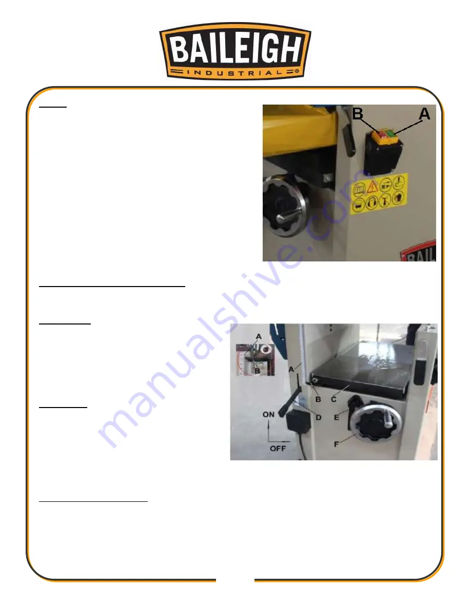
Power
1. Once a properly rated plug is connected, plug
power cord into outlet. Press the green on button
(A, Fig. 4) to start. Press the red off button (B,
Fig. 4) to stop.
Planer Controls and Adjustments
Referring to Figure 5:
Power Feed
1. Placing the planer power feed handle
(D) in the up position turns the planer
power feed on (see arrow).
2. Placing the handle in the down position
turns the power feed off.
Table Lock
1. Turn the table lock (E) clockwise to lock
the height adjustment handwheel (F)
and secure the planer table (C) in its
selected position.
2. Turn the table lock (E) counterclockwise
to release and permit table adjustment.
Table Height Adjustment
The planer table height is set as follows:
1. Unlock the table lock (E).
2. Rotate the height adjustment handwheel (F) clockwise to raise the planer table (C),
counterclockwise to lower.
Figure 4
Figure 5
Содержание JP-1250-1.0
Страница 45: ...42 42 CUTTER BLOCK GUARD AND OUTFEED ASSEMBLY PARTS DIAGRAM ...
Страница 48: ...45 45 CUTTER BLOCK ASSEMBLY PARTS DIAGRAM ...
Страница 51: ...48 48 BASE ASSEMBLY PART DIAGRAM ...
Страница 54: ...51 51 INFEED TABLE ASSEMBLY PARTS DIAGRAM ...
Страница 56: ...53 53 DRIVE AND MOTOR ASSEMBLY PARTS DIAGRAM ...
Страница 58: ...55 55 PLANER TABLE ASSEMBLY PARTS DIAGRAM ...
Страница 61: ...58 58 WORKING FENCE ASSEMBLY PARTS DIAGRAM ...
Страница 63: ...60 60 NOTES ...


