18
18
5. Check that the power cord has not been damaged during installation.
6. Install the electrical box cover.
7. With power connected and the main disconnect turned ON, the control panel will be lit.
8. Push the table up button to raise the table and the table down button to lower the table.
9. If not, disconnect power to the machine, and switch the Black and White wires. DO NOT
move the ground wire.
INTERNAL COMPONENT IDENTIFICATION
A.
Anti-Kickback Fingers:
Provide additional safety for the operator.
B.
Serrated Infeed Roller:
Pushes workpiece toward the cutterhead.
C.
Chipbreaker:
Breaks off chips created by the cutterhead to prevent tear out and diverts the
chips to the dust port.
D.
Cutterhead:
Holds the carbide inserts in a longitudinal pattern that plane the workpiece.
E.
Pressure Bar:
Stabilizes the workpiece as it leaves the cutterhead and assists in deflecting
wood particles toward the dust hood.
F.
Outfeed Rollers:
Pulls the workpiece toward the outfeed table.
G.
Working Table:
Provides a smooth and level path for the workpiece as it moves through the
planer.
A
B
C
D
E
F
G
G
G
Содержание IP-2008-HD
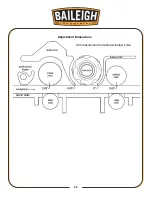
Страница 28: ...25 25 All measurements are shown below knife Adjustment Dimensions...
Страница 42: ...39 39 6 Loosen Nut on motor bracket 7 Remove belt 8 Remove cutterhead pulley...
Страница 46: ...43 43...
Страница 50: ...47 47 PARTS DIAGRAM...
Страница 51: ...48 48...
Страница 52: ...49 49...
Страница 53: ...50 50...
Страница 54: ...51 51...


