23
23
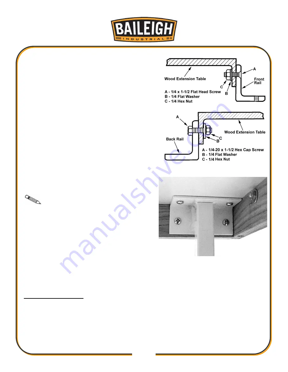
11. Install the three 1/4" flat head screws and
hardware into the holes in the front edge of
extension table. Finger tighten only.
12. Install the three 1/4" hex cap screws and hardware
into the holes in the rear edge of extension table.
Finger-tighten only.
13. Re-check the table for alignment, make further
adjustments if necessary, then tighten all screws
and nuts.
14. For the 50” tables, Mount the two legs to the
inside corners of the extension table using the
eight screws provided.
Note
: If you are using a mobile base
under your saw, you may need to shift the
placement of the legs so they rest properly upon the
mobile base.
15. Adjust the footpads on the legs counterclockwise
until they reach the floor, then tighten the nut.
16. Position the fence tube onto the front rail so that
the tube extends approximately 6” beyond the
rail on each end.
17. Install and tighten the fence guide tube to the front rail.
Install the Miter Gauge
1. Slide the miter gauge into the T-slot on the left-hand side of the blade.
Содержание TS-1040P-30-V2
Страница 47: ...44 44 TABLE CABINET PARTS DIAGRAM A...
Страница 50: ...47 47 TRUNNION MOTOR PARTS DIAGRAM B...
Страница 56: ...53 53 FENCE 30 50 PARTS DIAGRAM D...
Страница 58: ...55 55 FENCE RAIL 30 50 PARTS DIAGRAM E...


