34
34
Miter Gauge
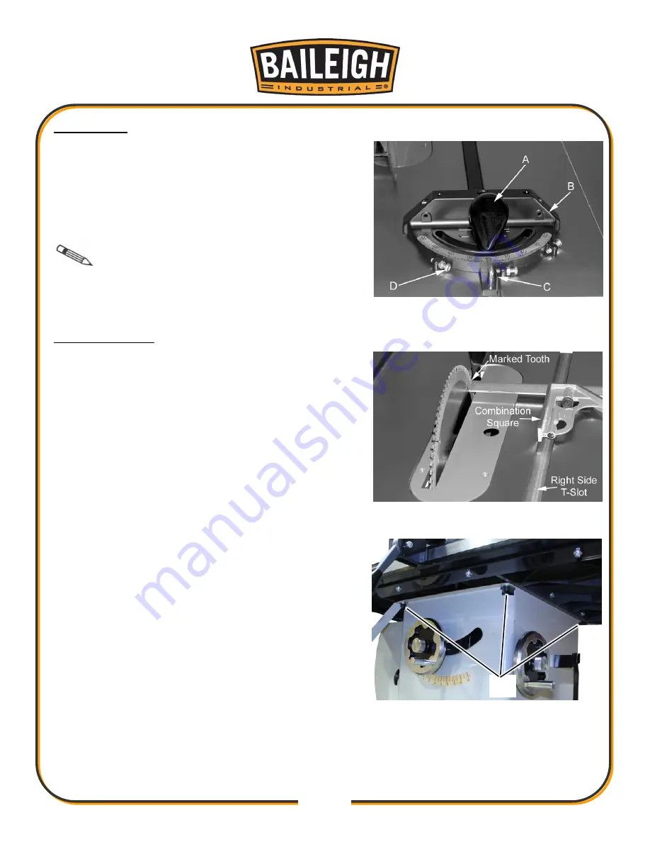
1. Operate miter gauge by loosening the lock knob (A)
and turning the miter body (B) to the desired angle.
To move gauge beyond index stops of 45º and 90º,
flip down the stop (C).
2. Adjust index stops by turning one of three
adjustment screws (D).
Note
: Always make test cuts. Do not rely
solely on miter gauge indicator marks. There are holes
in the miter gauge body that will allow you to mount a
wooden extension fence.
Blade Alignment
Blade alignment with the table is adjusted at the
factory. After a period of use, or, after moving the saw
to another location, the blade may no longer be
aligned with the table.
To check and align the blade:
1. Disconnect the saw from the power source.
2. Raise the blade guard up a way from the blade.
3. Choose a tooth on the back (output) side of the
blade and position the tooth slightly above the table
insert.
4. Mark the tooth with a marker.
5. Measure the distance from the side of the blade to
the right T-slot edge using a combination square.
Make sure to measure between the teeth not on
the tooth.
6. Rotate the blade toward the front so that the
marked tooth is just above the insert. Measure the
distance from the side of the blade to the right T-
slot edge. The two measurements should be the
same.
7. If they are not the same, loosen four socket cap
screws (A, three shown) that hold the table to the
base.
8. Adjust the table to the blade and tighten the four socket cap screws firmly.
9. Check the alignment once again after tightening hardware.
A
Содержание TS-1040P-30-V2
Страница 47: ...44 44 TABLE CABINET PARTS DIAGRAM A...
Страница 50: ...47 47 TRUNNION MOTOR PARTS DIAGRAM B...
Страница 56: ...53 53 FENCE 30 50 PARTS DIAGRAM D...
Страница 58: ...55 55 FENCE RAIL 30 50 PARTS DIAGRAM E...


