18
18
ASSEMBLY AND SET UP
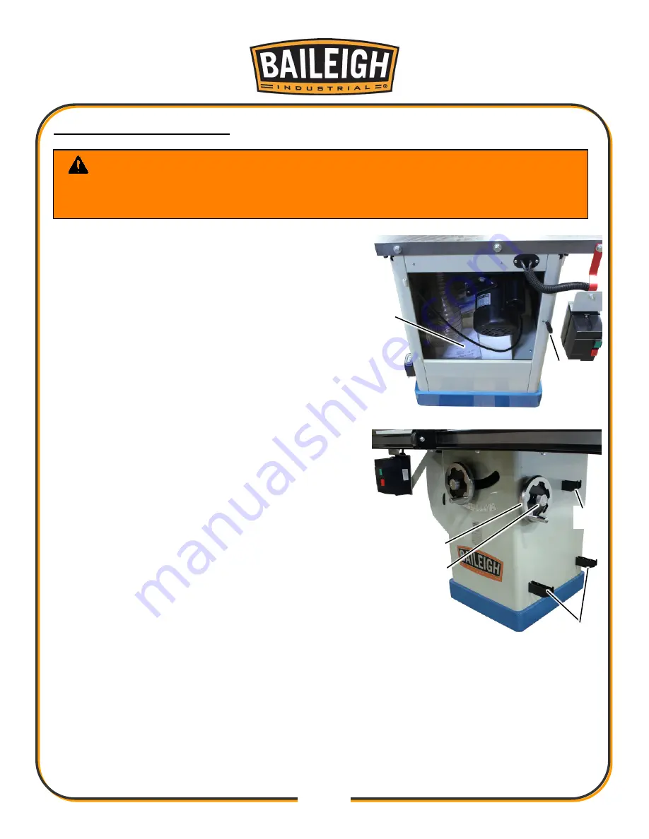
1. Using the handwheel for the saw blade height on
the front of the cabinet, raise the motor to the full
up position. This will allow for the boxes (A)
packed into the cabinet to be removed. If needed,
turn the tilting lead screw to tilt the motor and
trunnion into the 90° position.
2. Install the door by aligning the hinge pins and
inserting the door pins into the hinge sockets on
the cabinet.
3. Pull outward on the latch handle (B) and swing the
door closed.
4. Insert the latch handle into the slot and release the
handle.
5. Install the handwheels (C) onto the Blade Tilt
leadscrew shaft. Verify that the key is installed into
the shaft and engage the slots on the handwheel.
6. Install and use the center hand knob (D) to tighten
the handwheels to the shafts just enough so that it
is difficult to turn the handwheel to move the blade.
7. Loosen the hand knob 1/2 to 1 turn to allow the
handwheels to turn more freely during adjustment.
When tightening the hand knobs, Do Not over
tighten the knobs.
8. Using the M6 hardware, install the miter gauge
storage support (E) (smaller of the three supports)
and the two (same size) fence storage supports (F).
WARNING:
For your own safety, DO NOT connect the machine to the
power source until the machine is completely assembled and you read and
understand the entire instruction manual.
F
C
D
E
A
B
Содержание TS-1040P-30-V2
Страница 47: ...44 44 TABLE CABINET PARTS DIAGRAM A...
Страница 50: ...47 47 TRUNNION MOTOR PARTS DIAGRAM B...
Страница 56: ...53 53 FENCE 30 50 PARTS DIAGRAM D...
Страница 58: ...55 55 FENCE RAIL 30 50 PARTS DIAGRAM E...


