25
25
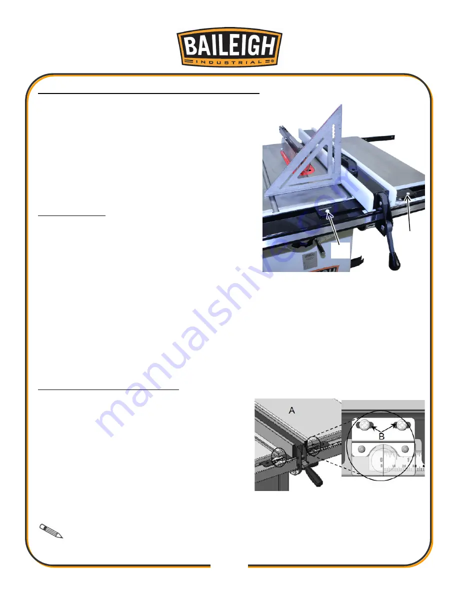
Align the Rip Fence Perpendicular (90°) to the Table
1. Disconnect and lockout power to the saw!
2. Place a square on the table against the fence and
look for a gap between the square and the fence
(bottom and top) or the table.
3. If needed, adjust either of the two plastic set
screws (E or F) to tilt the fence slightly and square
it to the table.
Level the Fence
The fence has a slide pad on the bottom which slide
over the top of the table. The fence should be parallel
to the table and sit approximately 1/16” (1.5mm)
above the table’s surface (so a thin work piece will not
get stuck or jammed under the fence).
1. Disconnect and lockout power to the saw!
2. Measure the table to fence gap at the outfeed (back) side and the infeed (front) side of the
table.
3. If needed, to level the fence, adjust the plastic set screws (E and F)
equally
, thereby raising
or lowering the front of the fence an equal amount on either side so as not to undo the
perpendicular adjustment.
Adjust & Align Rip Fence Pointer
1. Disconnect and lockout power to the saw!
2. Set blade to 90° and raise it to the maximum
height.
3. Move the fence until it lightly touches the right
side of the blade and push down the locking
lever to lock the fence in place.
4. With the fence locked in place against the blade,
loosen the pointer screws (B).
5. Line up the reference line on the pointer with the zero point on the tape and tighten the
pointer screws.
Note:
When changing blades, re-align the pointer with the zero points on the tapes
to account for thinner or thicker blades.
E
F
Содержание TS-1040P-30-V2
Страница 47: ...44 44 TABLE CABINET PARTS DIAGRAM A...
Страница 50: ...47 47 TRUNNION MOTOR PARTS DIAGRAM B...
Страница 56: ...53 53 FENCE 30 50 PARTS DIAGRAM D...
Страница 58: ...55 55 FENCE RAIL 30 50 PARTS DIAGRAM E...


