background image


22 

22 

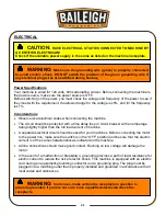
  Improper connection of the equipment-grounding conductor can result in risk of electric 

shock. The conductor with insulation having an outer surface that is green with or without 
yellow stripes is the equipment-grounding conductor. If repair or replacement of the electric 
cord or plug is necessary, do not connect the equipment-grounding conductor to a live 
terminal. 

  Check with qualified electrician or service personnel if the grounding instructions are not 

completely understood, or if in doubt as to whether the machine is properly grounded. 

  Repair or replace damaged or worn cord immediately. 


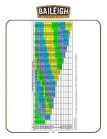
Extension Cord Safety 

Extension  cord  should  be  in  good  condition  and  meet  the  minimum  wire  gauge  requirements 
listed below: 


LENGTH 

AMP RATING 

25ft 

50ft 

100ft 

1-12 

16 

16 

14 

13-16 

14 

12 

12 

17-20 

12 

12 

10 

21-30 

10 

10 

No 


WIRE GAUGE 

 
An  undersized  cord  decreases  line  voltage,  causing  loss  of  power  and  overheating.  All  cords 
should use a ground wire and plug pin. Replace any damaged cords immediately. 


Power cord connection: 

1.  Turn the main disconnect switch on the control panel to the OFF position. 

2.  Unwrap the power cord and route the cord away from the machine toward the power supply. 

a.  Route the power cord so that it will NOT become entangled in the machine in any 

way. 

b.  Route the cord to the power supply in a way that does NOT create a trip hazard. 

3.  Connect the power cord to the power supply and check that the power cord has not been 

damaged during installation. 

4.  When the machine is clear of any obstruction. The main power switch may be turn ON to test 

the operation. Turn the switch OFF when the machine is not in operation. 


Содержание BS-712MS

Страница 1: ...AL HOLDINGS LLC IS PROHIBITED Baileigh Industrial Holdings LLC Inc does not assume and hereby disclaims any liability for any damage or loss caused by an omission or error in this Operator s Manual re...

Страница 2: ...Saw is Running 23 Breaking in a Band Saw Blade 24 Metal Chip Indicators 24 Blade Terminology 25 Width of Blade 25 Length of Blade 25 Blade structure 26 Blade type 26 SETS 27 BLADE CARE 28 CHOOSING A S...

Страница 3: ...Coolant System 41 Gearbox Maintenance 42 Oils for Lubricating Coolant 42 Storing Machine for Extended Period of Time 42 PARTS DIAGRAM A 43 PARTS DIAGRAM B 44 Parts List For A And B 45 ELECTRICAL COMP...

Страница 4: ...n notice to Seller of any suspected defect in the Goods prior to the expiration of the warranty period The original end user must also obtain a RGA from Seller prior to returning any Goods to Seller f...

Страница 5: ...emedies provided under this Agreement or at law or equity Attorney s Fees In the event legal action is necessary to recover monies due from Buyer or to enforce any provision of this Agreement Buyer sh...

Страница 6: ...Description of the functional parts of the machine Capacity charts Setup and start up instructions Machine operation Scheduled maintenance Parts lists GENERAL NOTES After receiving your equipment remo...

Страница 7: ...zardous situation which if not avoided will result in death or serious injury WARNING Indicates a hazardous situation which if not avoided could result in death or serious injury CAUTION Indicates a h...

Страница 8: ...e or uncomfortable loud noises HIGH VOLTAGE USE CAUTION IN HIGH VOLTAGE AREAS DO NOT assume the power to be off FOLLOW PROPER LOCKOUT PROCEDURES BEWARE OF CUT AND PINCH POINTS Moving saw blade may res...

Страница 9: ...igh does not recommend or endorse making any modifications or alterations to a Baileigh machine Modifications or alterations to a machine may pose a substantial risk of injury to the operator or other...

Страница 10: ...k any part that appears damaged Check for alignment and binding of moving parts that may affect proper machine operation 15 Observe work area conditions DO NOT use machines or power tools in damp or w...

Страница 11: ...Weight 462lbs 210kg Shipping Dimensions 50 x 22 x 44 1270 x 559 x 1118mm TECHNICAL SUPPORT Our technical support department can be reached at 920 684 4990 and asking for the support desk for purchased...

Страница 12: ...ge painted surfaces Follow manufacturer s label instructions when using any type of cleaning product After cleaning wipe unpainted metal surfaces with a light coating of quality oil or grease for prot...

Страница 13: ...10 10 Shipping Container Contents 1 Saw 1 Base left end 1 Base right end 2 Base sides 1 Hardware bag includes 4 ea hex bolt and flat washers...

Страница 14: ...11 11 1 Stop bracket 1 Stop rod 1 Work stop 1 Saw bow guard w hardware 1 Drain screen 1 Lift handle w hardware 1 Support leg w hardware 2 Wheels w bearings 1 Axle w 2 hitch pins 2 flat washers...

Страница 15: ...to the floor Level the machine so that all the supporting feet are taking the weight of the machine and no rocking is taking place Follow these guidelines when lifting crane or hoist Always lift and c...

Страница 16: ...ING The machine should be sited on a level concrete floor Provisions for securing it should be in position prior to placing the machine The accuracy of any machine depends on the precise placement of...

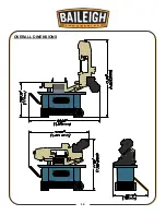
Страница 17: ...14 14 OVERALL DIMENSIONS...

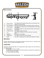
Страница 18: ...15 15 GETTING TO KNOW YOUR MACHINE A B C D E F G H I K J L...

Страница 19: ...ise I Motor gearbox Drives the saw blade J Discharge Tray Directs the cut piece part from the saw K Speed knob 3 position gear selector to change blade speeds L Material stop bar For setting the lengt...

Страница 20: ...ls until they lock 3 Insert the axle into the holes on the right end panel as shown 4 Push each wheel onto the axle slip on a flat washer and secure each with a cotter pin WARNING For your own safety...

Страница 21: ...saw and place onto the assembled wheelbase 7 Secure with the 4 bolts and flat washers provided 8 Screw the threaded stop rod into the vise base and assemble the material stop onto the stop rod as show...

Страница 22: ...ion Use the access door on the rear of the machine when attaching the nuts Attaching the Support Bar The support bar helps to prevent the saw from tipping over when the bow is in the vertical sawing p...

Страница 23: ...hine from the power source 2 Remove the coolant return hose from the drain pan fitting and the strainer basket 3 Slide the tank out from the lower compartment 4 Remove the strainer basket and fill the...

Страница 24: ...indicated on the machine All line connections should make good contact Running on low voltage will damage the motor In the event of a malfunction or breakdown grounding provides a path of least resist...

Страница 25: ...ted below LENGTH AMP RATING 25ft 50ft 100ft 1 12 16 16 14 13 16 14 12 12 17 20 12 12 10 21 30 10 10 No WIRE GAUGE An undersized cord decreases line voltage causing loss of power and overheating All co...

Страница 26: ...the cut off piece can move sideways after it is cut off Otherwise it could get wedged against the blade and thrown violently Never turn the saw ON before clearing everything except the work piece ben...

Страница 27: ...s approximately 300cm of the material should be cut for breaking in If large work piece dimensions are to be cut we recommend a breaking in period of about 15 minutes After breaking in you may slowly...

Страница 28: ...easured from gullet to gullet G GAUGE The thickness of the blade H TOOTH SET The distance a tooth is bent from the blade I KERF The width of material that is removed by the blade when cutting Width of...

Страница 29: ...for transversal or inclined cutting of solid small and average cross sections or pipes in laminated mild steel and gray iron or general metal POSITIVE RAKE TOOTH 9 10 positive rake and constant pitch...

Страница 30: ...l use for materials with dimensions superior to 5 mm Used for the cutting of steel castings and hard nonferrous materials WAVY SET Set in smooth waves This set is associated with very fine teeth and i...

Страница 31: ...G A SAW BLADE A general purpose blade is furnished with this band saw To achieve a quality economical and efficient saw cut the following points must be taken into consideration Type of material being...

Страница 32: ...29 29...

Страница 33: ...ides Forcing a large width blade to cut a small radius Using a blade with an improperly finished weld joint Allowing the blade to run when not in use NEVER leave an unattended blade running MATERIAL S...

Страница 34: ...turning the clamp handle counterclockwise ccw 2 Rotate the saw bow to the desired angle as shown on the red angle indicator 3 Lock the bow by turning the clamp handle clockwise cw WARNING Make sure th...

Страница 35: ...hold the bolt in position and tighten the nut to the bracket to hold the bolt in place 3 If the saw completes the cut and continues to run adjust the stop bolt T out 4 If the saw shuts off before the...

Страница 36: ...to remove any sag of the blade between the bearing wheels 4 Now turn the knob an additional 1 3 4 2 turns clockwise cw This equals approximately 2 300 lbs of blade tension Use the Dynametric Tension...

Страница 37: ...cal position and lock in place by turning the hydraulic cylinder off 6 Remove the 2 screws and open the hinged blade guard 7 Release the blade tension by turning the tension knob D counterclockwise cc...

Страница 38: ...de guide bearings have been adjusted at the factory Over time an adjustment will become necessary due to uneven blade wear or skewed cuts The side bearings have an eccentric shaft to allow for side to...

Страница 39: ...rive pulley cover 4 Run the saw and observe the blade The blade should run close to but not tightly against the pulley flange 5 Loosen the two hex bolts V as indicated 6 Turn setscrew W while observin...

Страница 40: ...cut plastics soft or medium soft aluminum wood and other light materials 3 After the speed change re connect power to the saw Note There is also a speed selection chart posted above the gear box Vert...

Страница 41: ...feed selector is used to control the blade feed rate and to lock the saw bow in the vertical position To increase the feed rate turn the knob counterclockwise ccw To decrease the feed rate turn the kn...

Страница 42: ...0 2 4 6 8 counterclockwise ccw to start the bow descent 11 Start the coolant flow slowly by turning the brass valve counterclockwise ccw 12 When the cut is finished the saw motor and coolant pump wil...

Страница 43: ...he machine and the area around it Lubricate threaded components and sliding devices Apply rust inhibitive lubricant to all non painted surfaces Thoroughly clean the machine Wipe and re grease the vise...

Страница 44: ...Accessing and Cleaning the Coolant System 1 Disconnect power from the saw 2 Remove the vinyl hose AB from the strainer basket and pull off of the drain fitting 3 Carefully remove the tank from the bas...

Страница 45: ...er of gear oil For reference use SHELL type gear oil or Mobil gear oil 90 Oils for Lubricating Coolant Any 10 1 water to coolant solution will work however we recommend Baileigh B Cool 20 1 water to c...

Страница 46: ...43 43 PARTS DIAGRAM A...

Страница 47: ...44 44 PARTS DIAGRAM B...

Страница 48: ...cket 1 13 Hand 1 125 Spring Adjusting Rod 3 8x130mm 1 14 Hex Hd Screw 5 16x3 4 4 126 Spring 1 15 Washer 5 16 x 18 x 2 4 127 Saw Bow 1 15 1 Spring Washer 5 16 4 127 1 Hex Hd Screw 5 16x1 1 4 4 16 Wheel...

Страница 49: ...Washer 5 16 3 147 2 Hd Screw 1 4x1 2 2 46 Support Rod 1 148 Magnetic Switch 1 47 Hydraulic Cylinder 1 149 Washer 5 16 2 48 Cylinder Cover 1 150 Spring Washer 5 16 2 49 Round Hd Screw 1 4x3 8 2 151 He...

Страница 50: ...Assembly 1 178 Blade Tension Sliding Block 1 83 Set Screw 5 16x3 8 1 179 Set Screw 5 16x3 4 1 84 Lead Screw 1 180 Hex Hd Screw 5 16x1 1 2 2 85 Key 5x5x20 1 181 Sliding Draw Block 1 86N Lead Screw Bra...

Страница 51: ...6 1 196N Gear Box 1 ELECTRICAL COMPONENTS Item Description and function Technical data Remark KM Magnetic Contactor AC1 12A 600V CNS 2930 BS 775 FR Overload Relay 12 0 18 0 14A 1x115VAC TH 12 SQ1 Cut...

Страница 52: ...49 49 WIRING DIAGRAM MAGNETIC SWITCH COOLANT PUMP MOTOR 110V POWER SOURCE LIMIT SWITCH BLACK WHITE GREEN...

Страница 53: ...1ph M PE 1 2 1ph 74kw 1720 rpm 110V 16A main motor 09kw 2850 rpm 110V 7A coolant pump motor SB1 SB2 SB3 E KM position L1 L 2 FU L1 L 2 FR 1 0mm 2 C1 C2 1 0mm 2 U2 V2 U V SA 1 0mm 2 1 0mm 2 1 ph 60Hz...

Страница 54: ...he material before the saw is started 7 Misaligned guides 8 Blade too thick for wheel diameter 9 Cracking of blade weld 1 Adjust to where blade just does not slip on wheel 2 Consult machine chart or h...

Страница 55: ...Reduce speed increase feed pressure Hard spots Increase feed pressure 5 Increase feed pressure by reducing spring tension 6 Remove blade twist inside out and reinstall blade 7 Increase tension to pro...

Страница 56: ...Blade is too coarse 1 Reduce speed and feed 2 Replace with a finer blade Blade is Twisting 1 Cut is causing the blade to bind 2 Too much blade tension 1 Decrease the feed pressure 2 Decrease the blad...

Страница 57: ...54 54 No Coolant at Nozzle 1 Valve not open 2 Insufficient coolant 3 Coolant motor burned out 4 Plugged coolant line 1 Open valve 2 Fill to 80 capacity 3 Replace motor 4 Unplug line...

Страница 58: ...55 55 NOTES...

Страница 59: ...56 56 NOTES...

Страница 60: ...TOWOC WI 54220 PHONE 920 684 4990 FAX 920 684 3944 www baileigh com BAILEIGH INDUSTRIAL HOLDINGS LTD UNIT D SWIFT POINT SWIFT VALLEY INDUSTRIAL ESTATE RUGBY WEST MIDLANDS CV21 1QH UNITED KINGDOM PHONE...

Отзывы: