Servicing the Chamber and Disc
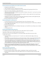
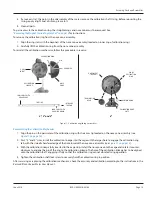
1 Remove the screws holding the bottom plate on the cover assembly
2 Remove the bottom plate
3 Remove the chamber retaining strap
4 Lift out the chamber and disc assembly
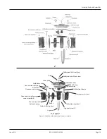
5 Inspect the chamber and parts (see
) for visible signs of wear The thrust roller and dovetail insert should be
replaced if worn Replace the chamber if wear is evident on disc spindle where it contacts the crossbar magnet drive or
the balls or if the disc plate is worn by foreign material If water deposits are found, remove any mineral deposits from
the disc and chamber interior surfaces Before replacing the chamber in the meter head, make certain that the area
surrounding the magnet in the meter head is clean
Valve Assembly
Removing the Valve Assembly
With the cover assembly removed, the valve assembly is exposed for service
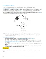
1 Remove the lock pawl (see
2 Turn the valve assembly counter-clockwise to unscrew it from the housing
3 Lift the valve assembly out of the housing
Replacing the Valve Assembly
If any portion of the valve assembly requires replacement, we recommend replacing the entire valve assembly
1 Check the O-ring for damage Clean or replace prior to reassembly
2 Drop in the new assembly, being certain the O-ring is installed
3 Turn the assembly clockwise to thread it into the housing
4 Drop the lock pawl back into position to lock in the assembly
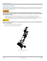
Valve
Assembly
Lock Pawl
Cover
Assembly
Low Flow
Register
High Flow
Register
Turbo Head
Assembly
Figure 14: Valve assembly
Servicing Parts and Assemblies
June 2016
RCS-UM-00076-EN-04
Page 19

