background image

 Page 44

Regalia Service Manual

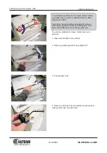
The main shaft needle position sensor disc mounts to 

the main shaft near the hand wheel. It is composed 

of an aluminium disk with a cutout for needle up and 

needle down positions. This disk is set on a flat on the 

Amara/Forte machines; however it does not follow 

the first screw in direction of motion rule. The second 

screw is the one set on the flat. The sensor board is 

mounted directly to the top of the control board .  

With the take-up lever in its highest position, the first 

screw is at the front and the edge of the cutout is 

aligned with the sensor. The 2nd screw is on the flat. 

The disk is centered front to back in the sensor slot. 

The take-up lever is up at this time.

There is a forked circuit board containing an 

emitter and a receiver for the encoder region. With 

the front cover removed, the cables connected 

and the machine powered on, the green “NEEDLE” 

LED on the right of the control board can be seen. 

It will turn on when the take-up lever is at its 

highest position, and stay on until the needle is at 

its lowest position. The LED is off until the take-up 

lever once again reaches its highest position and 

then turns on again. The main shaft encoder board 

(# QM20052) does not have any LEDs on the board.

Section 17: Electronic Information - Needle Position 

Sensor

Содержание Regalia BLRG20

Страница 1: ...Service Manual Model BLRG20...

Страница 2: ...Loop Lift and Needle Distance 32 Section 13 Adjusting Loop Lift and Needle Distance 33 Section 14 Adjusting Needle Height 36 Section 15 Adjustment of the Stop Finger 38 Section 16 Adjustment the Needl...

Страница 3: ...addition to the teaching aids found herein you will also find all of the tools listed that are necessary for adjustments If you need help in locating these tools for purchase please contact Baby lock...

Страница 4: ...ication main components Lubrication of hook Regalia 228 mm X 521 mm 9 X 20 5 Manual Mode Min 25 spm Max 2500 spm Regulated Mode Min 0 spm Max full speed 4 24 spi One stitch per quarter inch one stitch...

Страница 5: ...nsion assembly 3 hole thread guide motor pulley hook 3 5 mm Allen socket head cap screw class 8 8 5 6 Nm uses 4 mm Allen tool Front cover large Belt tensioner Drive train bracket 4 5 mm Allen set scre...

Страница 6: ...t Lube Replacement Lube Replacement Lube Replacement Lube Rep Lube Kit Box 1 Red QM49301 2 Blue QM49302 3 Yellow QM49303 4 Green QM49304 5 Orange QM49305 6 Purple QM49306 1 6 Kit QM49262 Lubricant Typ...

Страница 7: ...read mast reposition and tighten the jam nut 10 mm open end wrench 2 Check Inspect Test the condition of the thread guides 1 2 3 thread stirrup 4 thread guide 5 and needle bar thread guide 6 for any a...

Страница 8: ...crew under the Quick Set Tension assembly on the front cover casting and pull the tension assembly out just far enough to loosen the set screw on the barrel step 4 so the center split bolt can be remo...

Страница 9: ...ring strength push the split bolt all the way in to the barrel and tighten the barrel set screw loosened in step 4 Shoulder 7 Ensure that the top tension barrel is pushed into the shoulder Assembly is...

Страница 10: ...f the spring is critical If it is too weak or too strong it will not take the thread up properly and this will cause stitching issues 3 With the spring strength set properly ensure the center split bo...

Страница 11: ...cover 3 Remove the needle plate screws with a 3 flat screwdriver Remove the needle plate 4 Loosen the levelling screw 1 full turn with a 5 mm handle hex tool This will take any bind off the two large...

Страница 12: ...rame screws with a 4 mm hex tool 6 Remove the large center upper frame screw with a 4 mm hex tool 7 Remove the two large and three small front cover screws 5 total circled with 4 mm and 3 mm hex tools...

Страница 13: ...he right throat light NOTE Once the front cover is removed and the wiring harness in the above step is disconnected neither throat light will work because the right and left throat lights are wired in...

Страница 14: ...ing and the shaft 7 places Lubrication Schedule The Regalia lubricating schedule should be followed every 24 months or 10 million stitches whichever comes first to ensure top mechanical performance 1...

Страница 15: ...and presser bars on the top two bearings and also on the bottom two bearings as shown in the bottom photo Work the oil up into the bottom two bearings by turning the hand wheel for the needle bar and...

Страница 16: ...and needle bar driver 3 places 4 Green IsoFlex NCA 15 Inside caged needle bearings 2 places Section 3 Regalia Lubrication Continued 3 4 4 5 5 5 5 Orange GLY 151 Add grease sparingly to the presser ba...

Страница 17: ...is application is based upon sewing for eight hours of machine time If the machine is used less lubricate the hook less frequently After the lubrication of the hook it is recommended that you sew on s...

Страница 18: ...t the collar to remove ax ial play not the hook shaft pulley The setting can be thrown off which may make needle to hook distance adjustment impossible The Regalia utilizes long collars with two screw...

Страница 19: ...rew is then tightened compounding the tightness of the first screw thus securing and assuring that timing will not change NOTE The brass counterweight position is critical both axially and rotationall...

Страница 20: ...minimal to no play is detected Provisionally set the screws Check that the shaft has minimal play and no tightness from the collar being too tight by rotating the shaft through a few 360o rotations C...

Страница 21: ...uare to the machine as possible The two baseplate screws should be tight on the back casting NOTE If the front cover has been removed to service the machine the M10 adjustment screw should be flush or...

Страница 22: ...rock IMPORTANT If the two front base plate screws are not tight or if the M10 screw is extended out of the casting when the front base plate is installed and tightened then backing of the screw to ra...

Страница 23: ...eeth and any of the driven components Confirm also that there is an Immediate Transfer of Motion between the handwheel and the hook IMPORTANT Do not over tighten the belt as this will make the machine...

Страница 24: ...ring tension will be sufficient to hold the fabric properly during stitching and also keep the presser bar from knocking at high speeds The customer may be tempted to change the foot height at the jam...

Страница 25: ...reason See previous page If a correction is necessary Turn the hand wheel until the needle bar is at its lowest position This is the position where the presser bar is also in its lowest position Place...

Страница 26: ...M40133 under the hopping foot Loosen screw C through the machine front cover access hole 3 mm Allen driver While holding the tool in screw C and pushing down on the tool to maintain internal assembly...

Страница 27: ...needle watching for the tip to wobble The tip will not wobble if the needle is straight The needle must be centered in the stitch hole of the needle plate Check with needle eye flush with the needle p...

Страница 28: ...k Assure the small throat LED light strip connec tion on the back frame casting will not be pinched when the cover is replaced Check Assure the small throat LED light strip connec tion on the front co...

Страница 29: ...ection board the needle laser and light ring do not cover the head frame needle position adjust ment screws and will not be pinched when the front cover is installed Check Assure the wire in the botto...

Страница 30: ...will go on evenly and not bind Section 10 Replacing Front Cover Continued NOTE Back frame casting screw and tool sizes Back Screws M5x80 five quantity Middle Screws M5 x 55 top and M5x80 bottom 1 eac...

Страница 31: ...n screws F G and H through access holes two or three turns Loosen screws D and E two or three turns and back off screw C a little Push the head frame back against the main frame so that screw C touche...

Страница 32: ...center Place the loop lift clamp with special protective compression pad on the needle bar and set the thumbscrew lightly Place the 2 2 mm feeler gauge between the clamp and the bottom of the head fra...

Страница 33: ...the basket needle guard be rotated down out of the way to allow correct adjustment of the needle distance setting Rotate the basket out of the way to facilitate the needle distance adjustment IMPORTA...

Страница 34: ...urning and colliding with the needle NOTE When the hook screws have been loosened the adjustments of the loop lift and needle distance are possible since the hook can be moved radially as well as axia...

Страница 35: ...he machine If you have to push hard to get the needle to deflect then the needle is brushing hard against the hook The needle should only lightly brush against the hook to prevent undesirable hook wea...

Страница 36: ...ming has first been set correctly Check The needle height must be set so that when viewed from behind as shown and with the hook point flush with the right side of the needle the bottom of the hook po...

Страница 37: ...Ensure that the needle bar thread guide hole is straight towards the front of the machine If correction is necessary slightly loosen the needle bar driver screw while holding the needle bar with the o...

Страница 38: ...thread will get stuck around the stop finger and may jam the machine and damage the hook If an adjustment is necessary Loosen screw A and adjust the stop finger so the proper clearance is achieved IM...

Страница 39: ...ht with the cylinder height gauge so loop lift and needle distance will then need to be reset NOTE The Needle Height Cylinder Tool part number QM40131 REV C fits all Baby lock machines to date January...

Страница 40: ...stment is necessary hold onto the needle bar with one hand while loosening the screw with your other hand Raise or lower the needle bar as needed Rotate the needle bar until the hole in the needle bar...

Страница 41: ...ill supply 1 Amp of current at the supplied AC voltage Outlet Power is 120 watts maximum Fuse The machine uses a replaceable QM20059 4 0 A slow blow fuse 5 mm x 20 mm 250V located in the fuse holder a...

Страница 42: ...ensor board motor motor encoder bracket and fan No Machine Power If the machine has no power check the most obvious things first Power at source outlet Cord connected properly at source outlet and mac...

Страница 43: ...in white If the power supply has failed there will be no power at all to the machine no handlebar screens no lights etc However it is more likely that the fuse has blown if there is no power to the ma...

Страница 44: ...e cutout is aligned with the sensor The 2nd screw is on the flat The disk is centered front to back in the sensor slot The take up lever is up at this time There is a forked circuit board containing a...

Страница 45: ...rmly remove the handwheel screw with a 5 mm hex tool counterclockwise You may want to use the L hex tool for more leverage Install the 8 mm frame screw into the handwheel while holding the handwheel f...

Страница 46: ...ion 17 Electronic Information Removing Handwheel Continued Handwheel with 8 mm frame screw Handwheel fixing screw and washer at the side Back of machine with handwheel removed Rear LEDs and circuit bo...

Страница 47: ...7 Section 17 Electronic Information Replacing Handwheel While holding the handwheel firmly replace the screw and washer and tighten the screw firmly with a 5 mm hex tool to insure the handwheel is wel...

Страница 48: ...processor as well as other circuitry IMPORTANT The machine should be turned off when wiring is being unplugged or plugged back in during all testing IMPORTANT Proper ESD electrostatic discharge precau...

Страница 49: ...ply then the Control Board should be replaced If the LEDs come back on with everything unplugged but the above two items begin plugging the cables back in one at a time powering off between the connec...

Страница 50: ...isconnected has a bad connection or is damaged the display may still boot up past the splash screen However the touch screen will not update or change anything when touched The handlebar switches are...

Страница 51: ...nnections The two small LEDs D38 D39 above the con nection to the rear panel on the right for the rear handlebar connection function similar to those on the previous page for the front but for the rea...

Страница 52: ...er receive signal from carriage motors D36 Transmit signal to front display Pro Stitcher D37 Receive signal from front display Pro Stitcher D38 Rear display receive signal D39 Rear display transmit si...

Страница 53: ...J1 the front light ring and the front handlebar connection board QM20035 mounted on the inside of the back machine frame casting Circled left Two mini USB connectors for front handlebar con nection on...

Страница 54: ...llow wires to J9 Control Board right receptacle Multiple white and yellow wires from Control Board to J4 on the rear connection panel board circled at the bottom of image to the left Rear connection p...

Страница 55: ...T The two mini connectors for the Carriage X encoder and the Machine Y encoder have a tip and three rings All four conductors must make contact or the encoders will not work The cable must be plugged...

Страница 56: ...o the control board J8 connection From there a long cable takes the power to the front nose cover board J2 connector Power then passes from the front nose cover board to the Pro Stitcher black box via...

Страница 57: ...1 Multiple white and yellow wire connection from Control Board J2 Pass through power from rear connection power to front nose cover board J3 Front Display communication from Control Board J9 Needle la...

Страница 58: ...ess contains right LED light strip connection Quick Set Tension connection Thread Break Sensor connection J7 Large white connector for wire harness with many white and yellow wires for front machine c...

Страница 59: ...tor driver board NOTE if this is disconnected from the motor driver board the machine will run full speed when the start pause button is pressed J1 7 pin connection to Control Board Motor Driver Board...

Страница 60: ...ol Board to front nose cover board front handlebar connection board and LED light rear strip NOTE The front and rear LED light strips are wired in series both must be plugged in to work QM23017 Cable...

Страница 61: ...d for Pro Stitcher black box tablet power when connect ed with an additional cable provided with the Pro Stitcher at front nose cover board QM20026 3 Cable Front USB Control Board Gen3 Communications...

Страница 62: ...QM20045 Cable Outlet GND Gen3 QM20051 Cable Power MD to PSDC Gen3 From power supply to motor driver board QM20029 Cable Rear Main Gen 3 From Control Board to rear connection panel board QM20030 Cable...

Страница 63: ...te Power Gen3 Remote power on off from power supply to Control Board QM20027 Cable Wiring Harness Front Casting From Control Board to Quick Set Tension thread break sensor and LED light rear strip NOT...

Страница 64: ...ngs will also change The customer may be tempted to recalibrate tensions thinking that it will fix tension issues Calibrating the tensions when not needed or incorrectly will more likely cause more no...

Страница 65: ...ose cover screw 3 mm hex tool With the cables still connected push the cover and wires aside at the hole where the wires enter the machine The LED could be always on or always off Thread the machine t...

Страница 66: ...ered off and then back on again 5 It is normal for the bobbin area light to always be on 6 The Baby Lock Screen displays 7 The machine will do a long beep which indicates the machine Control Board pro...

Страница 67: ...t of the battery icon in the lower right corner of the display 3 On the pop up menu select settings 3 parallel lines 4 On the 2nd pop up menu select settings again 5 Select Apps 6 Select Regalia 7 Sel...

Страница 68: ...in the designated USB port on the bottom right side of the front display Look for the message in the bottom bar that confirms a USB drive has been inserted If it doesn t appear reinsert the USB drive...

Страница 69: ...e the display software Touch the Select Version box and then select the filename of the update file you downloaded To update the machine software 1 Insert the USB drive into the USB port on the bottom...

Страница 70: ...message box appears select New and Install 4 Be patient as this will take a few minutes 5 Confirm that you want to overwrite the current software with the new software by choosing Install If you decid...

Страница 71: ...read guide 3 2 Continue to three hole thread guide 4 Wrap all three holes from back to front being careful not to cross threads If delicate threads are breaking skip one or two holes to lessen tension...

Страница 72: ...lation Touch the Cruise button and specify the stitches per inch SPI and stitches per minute SPM cruise settings Machine starts to stitch immediately at the chosen SPM cruise speed when the Start Stop...

Страница 73: ...s property of and proprietary to baby lock Disclosure without express written permission is prohibited by law Copyright 2017 by baby lock QM20038 QM20040 Optional Rear Handles Optional 7 Touch Screen...

Страница 74: ...nd screw Safety Ground Signal Ground QM23032 Power enable cable QM20040 CN501 CN101 FG Faston Terminal TB501 TB502 Casting ground screw This document is property of and proprietary to baby lock Disclo...

Страница 75: ...series QM20032 J8 Front Casting Wiring Harness J11 J9 X and Y Encoder Input J14 J7 Power Supply Enable J13 J12 To Bobbin LED board QM20036 LED Control Switching LED driver Light Ring Serial to USB con...

Страница 76: ...solators 5VDC Independent 5VDC Regulator J5 48V Input From power supply Cable QM20051 Direct connection to Control Board J1 This document is property of and proprietary to baby lock Disclosure without...

Страница 77: ...20026 2 Communications Power 7 Touch Screen Display Assembly QM29302 0100 Pro Stitcher J9 Interface on QM20034 QM20043 This document is property of and proprietary to baby lock Disclosure without expr...

Страница 78: ...J10 J8 Remote Power Switch QM20034 Light Ring QM20037 Remote on off power cable from rear board QM20040 QM20043 QM23031 QM20026 1 Wire harness from Control board QM20026 1 QM20026 3 Rev Description Ap...

Страница 79: ...e Diamond key on the handlebar The machine will run the burn in process starting slow to full speed in steps and then back to slow again in steps over and over until turned off 2 To stop burn in turn...

Страница 80: ...Page 80 Regalia Service Manual NOTES...

Отзывы: