


Carry & Carry XL
Seite /
Page
5
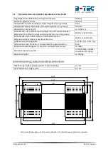
3.
Technische Beschreibung und bestimmungsgemäße Verwendung der Hebebühne
/
Technical Description and Intended Purpose of the Lift
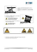
Die Hebebühnen Carry und Carry XL sind pneumatische Hebebühne mit Scherensystem für vierrädrige
Fahrzeuge mit einer Lastverteilung von ca. 3:2 und einem Gesamtgewicht bis 3300 kg (Carry) bzw.
3500 kg (Carry XL). Die bestimmungsgemäße Verwendung ist das vorübergehende Anheben von
vierrädrigen Fahrzeugen für Karosseriearbeiten. Das Fahrzeug steht auf den Rädern, wodurch eine
Arbeitshöhe von ca. 1280 mm für Karosseriearbeiten erreicht wird. Das Anheben erfolgt pneumatisch
durch einen Luftfederbalg bei ständigem Einrasten der Fallsicherung. Das Absenken erfolgt durch
Ablassen der Druckluft aus dem Luftfederbalg.
The lifts Carry and Carry XL are pneumatic scissor lifts for four-wheeled vehicles with a load distribution
of ca. 3:2 up to a total weight of 3300 kg (Carry) and 3500 kg (Carry XL). The intended purpose is the
temporary lifting of vehicles with four wheels for bodyworks. The vehicle stands on the wheels,
therefore it reaches a working height of ca. 1280 mm for body work. The lifting is actuated
pneumatically by an air-spring at constant latching of the safety gripping device to prevent falling.
Lowering is done by releasing the compressed-air of the air-spring.
Ersatzteilnummern siehe Abschnitt 3.6.
For spare parts ordering numbers see section 3.6.
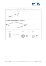
Für Abbildungen der Einbaubühnen siehe Abschnitt 8.4
Figures of the lifts for mounting in concrete / gratings see section 8.4
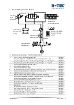
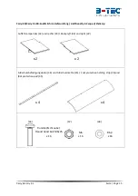
A - Mittelteil /
Middle desk
B
- Ausleger /
Outrigger
C
- Überfahrrampe /
Overtravel ramp
D - Auffahrrampe /
Ramp
E
- Überfahrsperre /
Stopper
F
- Gitterrost /
Grating
(Carry
-S / -EB
)
G - Handventil (Bedienteil) /
Hand-valve
H - Luftfederbalg /
Air-spring
I
- Befestigungswinkel Mitteltisch /
Mounting brackets middle desk
J
- Druckluftschläuche /
Pneumatic-hoses
Abbildung / Figure 3-1 – Carry-S
A
B
D
E
F
G
C
H
I
J


