


USER MANUAL
_
9
• Do not connect the DMX console to the fixture when it is controlled
via wireless. This could cause interference between the two modes of
operation.
controL PAnEL (mEnu oPtIonS)
A large number of settings are accessible from the fixture’s control panel.
A good working knowledge of it will enhance the fixture’s possibilities.
You can access the Main Menu by pressing the
key until the display
flashes.
Cycling through the menus is performed by pressing the
,
,
or
keys, as required:
Press the
key to select the desired menu.
Change the selection by pressing the
,
or
,
keys.
Confirm your selection by pressing the
key.
Exit a menu at any time by pressing the
key.
Notes:
You can return to the display by pressing the
or
keys from the
basic display.
If the screen fails to respond, hold the “Mode Esc” key down for at least 3
seconds to free up the display.
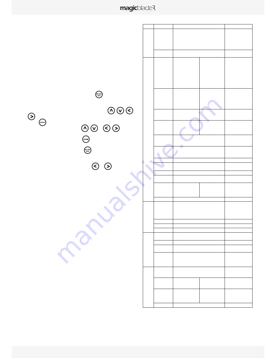
The fixture’s menu functions are described in the following table:
Address
Set Dmx Addr
A001~AXXX
DMX address setting
users
m
ode
User Mode
Stand Mode
Basic Mode
Extend Mode
User Mode A
User Mode B
User Mode C
User’s mode to change
channel numbers
Edit User
Max channel
PAN :
Preset User modes
options
Status
Addr via DMX
No DMX Mode
Pan Reverse
Tilt Reverse
Pan Degree
Feedback
Pan/Tilt Spd
Mic Sens.
Hibernation
ON/OFF
Close/Hold/Auto/Music
ON/OFF
ON/OFF
630/540
ON/OFF
Speed 1~ 4
0~99%
OFF, 01M~99M,15M
Add. via DMX
Auto run if no DMX
Pan Reverse movement
Tilt Reverse movement
Pan Degree Select
Movement Feedback
Reset Pan/Tilt
Sensitivity of Mic.
Stand by Mode
Service PIN
Service PIN
RDM PID
Set IP
Set LED BIN
Set Device ID
Password=XXX
xxxxxx
xxx.xxx.xxx.xxx
LED BINA
LED BINB
xx
Service Password“=050”
RDM PID Code
KlingNet Device ID
LED BIN
LED BIN
IP Addr
Fans Control
Head Control
Auto
High
Low
Head Fans Speed Mode
Select
Disp.Setting
Shutoff Time
Flip Display
Key Lock
DispFlash
02~<60m> <05m>
ON/OFF
ON/OFF
ON/OFF
Display shutoff time
Reverse 180 degree
Key Lock
No Signal Flash
Signal Select
DMX
WDMX
Art--Net
DMX
Wireless DMX
Art-Net
LED Control
Kling-Net OFF
Kling-Net RGB
Kling-Net RGBW
KlingNet confer
Kling-Net confer RGB
Kling-Net confer RGBW
Set Universe
xx
Art-Net Universe NO.
Temp. C/F
Celsius
Fahrenheit
Temperature switch
between °C/°F
Initial Pos.
PAN =XXX
Initial effect position
Wireless DMX
Act&Data Out
Rest WDMX
Act & Data Out
Reset Wireless DMX Mem
Trigger
DMX Value Disp.
Set To Slave
Auto Program
Music Ctrl.
PAN……
Slave1,Slave2,Slave3
Master / Alone
Master / Alone
DMX value display
Slave setting
Auto program
Music control
Reset Default
ON/OFF
Restore factory sett.
Info
Time Info.
Current Time
Ttl Life Hrs
Last Run Hrs
Timer PIN
Clr Last Run
XXXX(Hours)
XXXX(Hours)
XXXX(Hours)
Password=XXX
ON/OFF
Temp. Info
Head Temp.
XXX °C/°F
Software Ver
V1.0...
Software version
Network
IP,Mask,Mac
Network setting
test
Home
All
Pan&Tilt
Reset all motors
Reset Pan&Tilt
Test Channel
PAN ……
Test function
Manual Ctrl.
PAN =XXX
:
Fine adjustment of
parameters
Calibration
--Password--
PAN
:
Password “050”
Calbrate and adjust the
effects to standard/right
position
Preset
Select Prog.
Prog. Part 1 = Program 1 ~ 10 Program 1
Prog. Part 2 = Program 1 ~ 10 Program 2
Prog. Part 3 = Program 1 ~ 10 Program 3
Select programs to be run
Edit Prog.
Program 1
:
Program 10
Program Test
Step 01=SCxxx
Step 64=SCxxx
Testing program
Program in loop
Save and exit
Edit Scenes
Edit Scene 001
~ Edit Scene 250
Pan,Tilt,……
--Fade Time--
--Secne Time--
Input By Outside
Save and automatically
return
manual scenes edit
Scenes Input
XX~XX
Automat. scenes rec
Содержание MagicBlade R
Страница 1: ...USER MANUAL V 1 ENGLISH VERSION 01 05 2015...
Страница 2: ......
Страница 19: ...USER MANUAL _ 19...
Страница 20: ...www ayrton eu...


