


4
General Instructions for 230V Machines
Specific to Sanding Machines
The following will enable you to observe good working
practices, keep yourself and fellow workers safe and
maintain your tools and equipment in good working order.
Mains Powered Tools
• Tools are supplied with an attached 13 Amp plug.
• Inspect the cable and plug to ensure that neither are
damaged. Repair if necessary by a suitably qualified
person.
• Do not use when or where it is liable to get wet.
Workplace
• Do not use 230V a.c. powered tools anywhere
within a site area that is flooded.
• Keep machine clean.
• Leave machine unplugged until work is about to
commence.
• Always disconnect by pulling on the plug body
and not the cable.
•
Carry out a final check e.g. check the cutting tool
is securely tightened in the machine and
the
correct speed and function set.
•
Ensure you are comfortable before you start work,
balanced, not reaching etc.
• Wear appropriate safety clothing, goggles, gloves,
masks etc. Wear ear defenders at all times.
• If you have long hair wear a hair net or helmet to prevent
it being caught up in the rotating parts of the machine.
• Consideration should be given to the removal of rings
and wristwatches.
• Consideration should also be given to non-slip
footwear etc.
• If another person is to use the machine, ensure they are
suitably qualified to use it.
• Do not use the machine if you are tired or distracted.
• Do not use this machine within the designated safety
areas of flammable liquid stores or in areas where there
may be volatile gases.
• Check cutters are correct type and size, are
undamaged and are kept clean and sharp, this will
maintain their operating performance and lessen the
loading on the machine.
• OBSERVE…. make sure you know what is
happening around you and USE YOUR COMMON SENSE.
WARNING!! KEEP TOOLS AND
EQUIPMENT OUT OF REACH OF
YOUNG CHILDREN
KEEP WORK AREA AS
UNCLUTTERED AS IS PRACTICAL.
UNDER NO CIRCUMSTANCES
SHOULD CHILDREN BE ALLOWED
IN WORK AREAS.
WARNING! THE SANDING DISC
CANNOT BE DECLUTCHED FROM
THE BELT AND VICE VERSA, BOTH
FUNCTIONS ARE ACTIVE WHEN THE
MACHINE IS RUNNING. DO NOT
LEAVE LOOSE OBJECTS OF ANY
DESCRIPTION ON THE MACHINE IF
IT IS GOING TO BE USED.
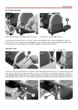
Once the sander is mounted, carry out any setting
operations and remove all tools used in the setting
operations (if any) and place safely out of the way. If you
are working long lengths of material arrange for extra
support beyond the boundary of the machine, and check
you have sufficient room to manoeuvre the material
through all the operations you will wish to carry out.
It is good practice to leave the machine unplugged until
work is about to commence; also make sure to unplug
the machine when it is not in use. Always disconnect by
pulling on the plug body and not the cable.
After fitting a new sanding disc, it is good practice
to lightly sand across the left side of the disc with a
reasonable sized (20mm x 50mm) piece of timber to make
sure the sanding disc is correctly ‘seated’ on the disc. The
sanding action will press the sanding disc firmly back
against the disc itself.
It is not good practice to wear gloves whilst sanding as
you tend to lose the ‘feel’ of the workpiece/sander contact,
but obviously this removes the safety barrier between
your fingers and the sanding surface. Remain focused and
exercise caution whilst sanding.
Содержание 107677
Страница 1: ...AW125BDS Mini Belt Disc Sander Code 107677 Original Instructions AT 09 02 2022 BOOK VERSION 02...
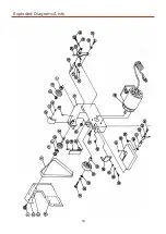
Страница 16: ...16 Exploded Diagrams Lists...
Страница 17: ...17 Exploded Diagrams Lists...
Страница 19: ...19 Wiring Diagram...


