Axminster 107677 Скачать руководство пользователя страница 14

14

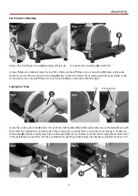
Changing the Abrasive Belt/Disc

DISCONNECT THE SANDER FROM 
THE MAINS SUPPLY

Remove the belt access cover as described on page 9 
Tracking the Belt, and place safely aside. While holding 
the belt, push in the tracking knob, thus releasing the 
tension on the belt and remove the abrasive belt (See figs 
31- 32).

Check the new belt for any signs of damage; fit the new 
belt by sliding it through the table (D) cutout and fit it over 
the three pulleys then release the tracking knob, putting 
tension back on.
Replace the access cover (d); reconnect the sander to the 
mains, turn on and check the belt is tracking correctly. If 
not remove the cover and go to page 9 for Tracking the 
Belt
. Replace the cover reconnect to the mains and check 
again.

DISCONNECT THE SANDER FROM 
THE MAINS SUPPLY

Remove the lift and shift handle (H), sanding disc table 
(C), dust extraction moulding (B) and place safely aside. 
Lift the edge of the disc and, gripping firmly, peel the 
disc away from the plate; turning the plate as required to 
free the entire disc (See fig 33). Remove and throw away. 
Remove any patches of abrahesive that have stuck to the 
disc and render the plate CLEAN.

Peel the cover from the adhesive surface and apply 
CAREFULLY to the flat surface of the cast iron disc. Place a 
piece of cloth in your hand or wear a glove, to firmly press 
the abrasive to the disc, it will be reinforced by a gentle 
sanding action across the face when you first use the new 
sanding disc. Replace the extraction moulding (B), sanding 
disc table (C) and lift and shift handles (F).

Fig 31.

Fig 33.

Fig 32.

D

Sanding Belt

Sanding Disc

Содержание 107677

Страница 1: ...AW125BDS Mini Belt Disc Sander Code 107677 Original Instructions AT 09 02 2022 BOOK VERSION 02...

Страница 2: ...should be worn The symbols below advise the correct safety procedures when using this machine 6 Cert No MM411 Axminster Tool Centre Ltd Axminster Devon EX13 5PH UK axminstertools com Type Mini Belt D...

Страница 3: ...M 1 Instruction Manual 1 Guarantee Card A B D C G H E F L M I J Having opened the box remove the top packaging and lift the machine out and place upon a clear flat surface taking care not to trap or p...

Страница 4: ...d size are undamaged and are kept clean and sharp this will maintain their operating performance and lessen the loading on the machine OBSERVE make sure you know what is happening around you and USE Y...

Страница 5: ...panying sharp flapping edges Always offer the workpiece to the belt disc so that the motion carries the work against the restraining surface i e the work stop or the table use the left hand side of th...

Страница 6: ...ing using the M8 washer I and M8 x 20mm lift and shift handle G Clamp the table in position See figs 2 3 and 4 NOTE You my find it easier if you remove the lift and shift handle G and screw the clampi...

Страница 7: ...le C M6 x 15mm lift and shift handles H and M6 washers J Line up the table C pins with the machined L shaped slots on either side of the sanding disc push the table in until fully home See figs 7 8 Re...

Страница 8: ...uare on the sanding disc table C and check that the table is perpendicular to the sanding disc If it requires adjustment loosen the two lift and shift handles H adjust until correct and re tighten the...

Страница 9: ...D until it is perpendicular to the belt 90 Square perpendicular to sanding belt Using a Hex key fine adjust the table if the square still does not line up correctly The clamping nut beneath the table...

Страница 10: ...LY NEEDSTO BEVERY SLIGHT Adjusting the Platen The Platen f should be adjusted so that it almost touches the back of the abrasive belt If it requires adjustment loosen the two caphead screws g that sec...

Страница 11: ...he Belt Reconnect switch on and check again If everything is fine switch off and wait until the machine has come to a complete stop DISCONNECTTHE SANDER FROM THE MAINS SUPPLY Dust Extraction The dust...

Страница 12: ...ve disc Belt guard Pointer Pointer rest screw Pointer rest screw Pointer A D C B E F H G A AW125BDS Belt and Disc Sander E Mitre Fence B Dust Extraction Moulding F Rubber Feet C Sanding Disc Cast Iron...

Страница 13: ...3 Illustration and Parts Description Platen Clamping Knob Belt Access Cover Disc Guard Dust extraction outlet Dust extraction outlet Chassis On Off On Off Control Box Grub screw for levelling the tabl...

Страница 14: ...ver reconnect to the mains and check again DISCONNECTTHE SANDER FROM THE MAINS SUPPLY Remove the lift and shift handle H sanding disc table C dust extraction moulding B and place safely aside Lift the...

Страница 15: ...LEM POSSIBLE CAUSE REMEDY Motor will not run 1 Defective or broken ON OFF switch 2 Defective or damaged switch cord 3 Defective or damaged switch relay 4 Burned out motor 5 Blown fuse 1 3 Replace all...

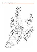
Страница 16: ...16 Exploded Diagrams Lists...

Страница 17: ...17 Exploded Diagrams Lists...

Страница 18: ...tic Washer 1 33 Washer 1 34 Belt Wheel 1 35 Insert 1 36 Bolt 1 37 Screw 1 38 Table 1 39 Nut 1 40 Washer 1 41 Bolt 1 Part Description Qty 42 Handle 1 43 Spring 1 44 Screw 1 45 Screw 3 46 Motor 1 47 Scr...

Страница 19: ...19 Wiring Diagram...

Страница 20: ...ars For more information visit axminstertools com 3years Axminster Tools Axminster Devon EX13 5PH axminstertools com The packaging is suitable for recycling Please dispose of it in a responsible manne...

Отзывы: