Set Up and Adjustment
15
7
8
10
11
6
5
9
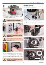
Using the supplied 24mm spanner (L), remove the bolt (a)
and clamping block (b) from the spindle. Place safely aside
the spacer collars (c) and shims (d), see fig 10-11.
NOTE: Removing the insert rig from the arbor, see fig 12
may depend on what size of cutter block is being used and
what your machining. Introduce a spacer collar (c) down over
the arbor, see fig 13 on page 16.
Turn the spindle by hand and press the spindle lock rod in,
until the lock engages into the spindle’s machined hole. Thus
locking the spindle in place, see fig 7-8.
Lock handle
b
a
d
c
NOTE: THE MACHINE WILL NOT
START WITH THE SPINDLE LOCK
ENGAGED, SEE FIG 9!
Spindle lock micro switch prevents the machine from starting
accidentally, avoiding damage to the spindle mechanism.
Spindle lock
Continues over...
CLEAN ALL SURFACES OF SPINDLE
ARBOR BEFORE MOUNTING THE
CUTTER BLOCK.
12
L


