3: A
dv
an
ce
d P
ro
gr
am
m
in
g • 1
9
Version 1.2 July 2010
tions are built into your IP-Intercom system. When
you have interconnections to other equipment, you
may need to extend the IP-Intercom logic func-
tions
to
and
from
these non-Livewire devices.
GPIO (General Purpose Input Output) can be
a complicated topic. In an IP-Intercom system,
GPIO is primarily used for the logic functions as-
sociated with Talk and Listen when we are com-
municating with other systems.
Intercom channel logic can be assigned to vir-
tual GPIO ports used for interfacing to intercom
sources that are external to your IP-Intercom sys-
tem. We saw on the External Sources configura-
tion page how we can name these external sources
and associate them with virtual GPIO channels
such as AUX 2. The Livewire GPIO configuration
page provides the logic link between these virtual
GPIO channels and physical connections to those
external sources so they will have Talk and Listen
capability.
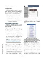
To continue with the example we started ear-
lier, you will recall we had determined that Milos
and Marc would both be assigned to GPIO Port
AUX 2. Here is where we will map that virtual GPIO
port to a real, physical GPIO connector by specifying
the IP address and physical port of the GPIO node that
is used for the remote contact closures to/from these two
users. In our example, Marc and Milos are both connect-
ed to Port 1 of the GPIO node at 192.168.0.110. We must
also map that GPIO port back to our virtual GPIO AUX
2 so the communication will be bidirectional. The chan-
nel specified for that remote GPIO port would look like
this: 192.168.0.140/4 which is port AUX 2 of our IC.20
IP-Intercom station. As we determined on the External
Sources page, the Talk and Listen input pins for Milos
are input pins 1 and 2 (respectively) of this port and the
Talk/Listen input pins for Marc are input pins 4 and 5.
When Milos wants to LISTEN, the IC.20 must be in
TALK mode (closure to input pin 1). When Milos wants
to TALK, the IC.20 must be in LISTEN mode (closure
to input pin 2).
Whenever we want to
Talk to
our friend Milos, out-
put pin 1 on this same port is activated. When we want
to
Listen to
Milos, output pin 2 is active on Port 1 of the
GPIO node at 192.168.0.110.
It is very important to understand the logic of Talk
and Listen as they apply to local and remote users. A lo-
cal IC.20 user will press Talk when he wants to talk. A
remote user will place the IC.20 channel into Talk mode
when he wants to Listen to the IC.20 local user. This
seems a bit strange but it is the same way a conversation
takes place. At any given point in time, one user is talk-
ing while the other is listening. When the IC.20 channel
is in Talk mode, the IC.20 user is talking and the remote
user is listening to him. The same logic follows through
to the Listen function. When the IC.20 local user must
Listen when the remote user Talks - so in order for this
exchange to take place, the IC.20 must be in Listen
Figure 3-8: IC.1 - Livewire GPIO
Содержание IP-Intercom System
Страница 44: ...Connecting GPIO 36 Version 1 2 July 2010...
Страница 45: ...Connecting GPIO 37 Version 1 2 July 2010...
Страница 48: ...Connecting GPIO 40 Version 1 2 July 2010...
Страница 52: ...Axia Audio a Telos Company 1241 Superior Ave Cleveland Ohio 44114 USA 1 216 241 7225 www AxiaAudio com...


