1: I
nt
ro
du
ci
ng I
P-
In
te
rc
om • 5
Version 1.2 July 2010
Analog Line Input Characteristics
•
Level: +4 dBu nominal (+24 dBu clip point)
•
Impedance : >/= 10 K Ohm balanced.
Analog Microphone Input Characteristics
•
Level: -83 to -28 dBu nominal, adjustable in 1
dB steps
•
Headroom: 20 dB above nominal
•
Impedance:
≥
4 KOhm balanced
Analog Output Characteristics
•
Level: +4 dBu nominal (+24 dBu clip point)
•
Impedance: < 50 Ohm
Note:
All microphone and line inputs are in-
ternally summed. All outputs are dual-channel
mono.
GPIO Port
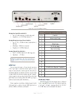
The rear panel contains a 15-pin control connector
with a logic input to mute the internal speaker, a logic
output to dim/mute the console speakers when the in-
tercom microphone is unmuted as well as a logic output
to signal when the intercom is being signaled (ringing).
A logic output is also provided, which follows the front
panel Line-Active warning LED. The GPIO pin assign-
ment are shown in the table that follows.
These signals are available as electrical signals on the
rack mount unit (or other Livewire GPIO ports) and as
software GPIO on all intercom channels.
IP-Intercom GPIO Connector Pinouts
Pin
Function:
1
Listen Active Lamp
2
3
Ring Lamp
4
Mic Mute Lamp
5
Line Active Lamp
6
7
8
9
10
11
12
Mute Preview/Speaker Command
13
14
15
AC (Mains) Power
The AC receptacle connects mains power to the unit
with a standard IEC power cord. The power supply has
a “universal” AC input, accepting from 90 to 240 VAC,
47-63 Hz. Fuses are located inside the chassis.
Figure 1-4: IC.20 - Rear Panel Callouts
Содержание IP-Intercom System
Страница 44: ...Connecting GPIO 36 Version 1 2 July 2010...
Страница 45: ...Connecting GPIO 37 Version 1 2 July 2010...
Страница 48: ...Connecting GPIO 40 Version 1 2 July 2010...
Страница 52: ...Axia Audio a Telos Company 1241 Superior Ave Cleveland Ohio 44114 USA 1 216 241 7225 www AxiaAudio com...

