background image

Version 1.2  July 2010

2: B

as

ic S

et

up a

nd O

pe

ra

tio

n • 1

0

• 

In all menus, selecting 

Back

 will take you back 

to the Home Page.

CALLSTACK (20-Station Panel)

This 

CALLSTACK

  channel  (found  only  on  the 

20-station rackmount panel and the 20-station Element 

console module) is used for monitoring and calling sta-
tions that are not assigned to a specific Talk/Listen chan-
nel on the user’s panel. The OLED lists up to four ring-
ing, active and last completed calls. Press 

Talk

 to talk 

to the present source displayed. You can use the 

Select


control to scroll through the call list.

• 

The 

Listen

 LED flashes yellow when the local 

user is being called by a station not assigned to 
one of the Talk/Listen channels on the called sta-
tion  panel,  and  continues  to  flash  for  approxi-
mately 40 seconds or until call is answered. 

• 

The 

Talk

 LED flashes red when a remote user 

is  attempting  to  Listen  to  you.  The 

Talk

  LED 

is solid red when you have selected Talk Mode. 
It  may  flash  red  to  indicate  a  fault  (attempt  to 
communicate with faulty or disconnected panel, 
route is locked out by studio IFB, system failure 
prohibits completing route, etc.)

Keypad (IC.20 only)

The keypad will be used for enhancements that will 

be  added  in  the  future.  In  a  networked  studio  environ-
ment,  there  are  many  possibilities.  Stay  tuned  -  we 

wouldn’t put it there if we didn’t have a plan for it!

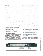
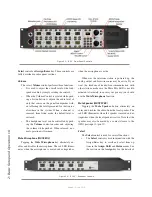
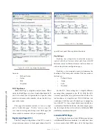
Film-Cap Buttons (IC.1 only) 

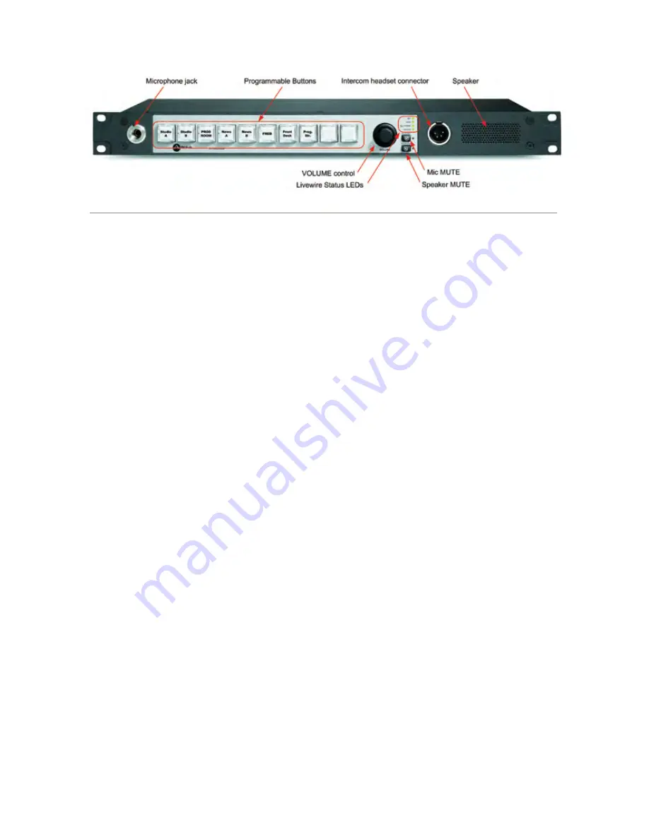
The 10-button Intercom panel shown in Figure 2-4 

features 10 film-cap buttons that are programmed in the 

web page setup of the IC.1. These buttons may be con-

figured as Talk or Listen buttons. They may also be con-
figured as combination Talk/Listen buttons that provide 

the equivalent of pressing both the Talk and Listen but-
tons on an IC.20 station. This allows an IC.1 user to open 
up full two-way communication with a user by pressing 
a single button.

Note  that  the  Film-Cap  buttons  cannot  be  pro-

grammed  from  the  front  panel  of  the  IC.1.  The  web 

page setup must be used to configure these buttons. See 

Chapter 3: Advanced

 Programming for details.

Console-Mounted Intercom Stations

Connecting  console-mounted  IP-Intercom  stations 

couldn’t  be  easier.  Each  of  these  modules  is  equipped 

with a CANBus RJ-45 connector. All data communica-

tion and power is provided by the CANBus connection. 

The  console-mounted  modules  are  highly  integrated 
with  the  Element  console  and  do  not  have  dedicated 
GPIO or audio connectors. 

To get started, simply connect the IP-Intercom con-

sole  module  to  the  CANBus  distribution  hub  in  your 
Element  console  using  a  CAT5-E  patch  cable.  Note 
that more than one IP-Intercom module in an Element 
console is unsupported so any setting of the ID selector 
switch on the circuit board will be acceptable.

Once  you  have  connected  the  Intercom  module,  it 

may  be  necessary  to  ensure  that  the  Element  knows 
about it. To do this, enter the Element capture mode by 
pressing both 

*

 and 

2

 keys on the Element keypad for 5 

seconds. When you see “

Capture

” displayed above each 

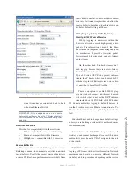
Figure 2-4: IC.1  Front Panel Controls

Содержание IP-Intercom System

Страница 1: ...IP Intercom System Installation User s Guide Manual Version 1 2 1 Aug 2010 IP Intercom Software 1 2 5 and up...

Страница 2: ...tions Le present appareil nu merique n emet pas de bruits radioelectriques depas sant les limites applicables aux appareils numeriques de les Class A prescrites dans le Reglement sur le brouillage rad...

Страница 3: ...y become available to determine if this is the case check our web site Contact us to determine if a newer release is more suitable to your needs Our electronic newsletter has announcements of major so...

Страница 4: ...he unit when you call so our Support Engineers can verify infor mation about your configuration and the conditions under which the problem occurs If the unit must return to Axia we will need your seri...

Страница 5: ...up 20 Station Panel 9 Assign 20 Station Panel 9 CALLSTACK 20 Station Panel 10 Keypad IC 20 only 10 Film Cap Buttons IC 1 only 10 Console Mounted Intercom Stations 10 Chapter Three Advanced Programming...

Страница 6: ...Introduction vi Version 1 2 1 Aug 2010 Microphone opens Speech in tones soft and mellow A new broadcast day...

Страница 7: ...er and console engine were now integrated but the most important studio ele ment the PC was stuck in the past interfaced with 100 year old analog technology The PC and console couldn t communicate in...

Страница 8: ...Introduction viii Version 1 2 1 Aug 2010 Who is so attuned that he may perceive the sound of one bit dropping...

Страница 9: ...Windows are currently under development and will be released in the near future Axia s IP Intercom products may operate as a stand alone intercom system The IP Intercom system also in tegrates seamles...

Страница 10: ...ff Headset There are numerous other manufacturers of these head sets that all use the following 4 pin wiring convention Pin 1 Mic common Pin 2 Mic hot Pin 3 Headphone common Pin 4 Headphone hot mono I...

Страница 11: ...d in the web browser configuration Button caps are manually labelled using your favorite word processor or spread sheet software Create the 1 2 inch square labels for these buttons Use your fingers to...

Страница 12: ...k from the front panel controls Pressing this button also triggers the IP Intercom panel to identify itself and re quest an IP address from a BootP server on the Ethernet network more on this later Au...

Страница 13: ...the in tercom microphone is unmuted as well as a logic output to signal when the intercom is being signaled ringing A logic output is also provided which follows the front panel Line Active warning L...

Страница 14: ...1 Introducing IP Intercom 6 Version 1 2 July 2010 Featureless paper this page would have been empty save for this haiku...

Страница 15: ...ic key Listen In a manner identical to the Talk button this key may also be used in two different ways You may press and hold the Listen key to listen momentarily You may also tap the Listen key to la...

Страница 16: ...microphone The red LED illumi nates when the microphone is muted and extinguishes when the microphone is active Whenever the intercom station is powered up the analog output and Livewire source may b...

Страница 17: ...rom the group Talk and Listen LED indicators illuminate to show group assignment state Tap the Group button to leave assignment mode and its LED extinguishes Assign 20 Station Panel The Assign key is...

Страница 18: ...nel shown in Figure 2 4 features 10 film cap buttons that are programmed in the web page setup of the IC 1 These buttons may be con figured as Talk or Listen buttons They may also be con figured as co...

Страница 19: ...or external sources if desired IP Intercom logic signals include an input to mute the audio feeding the preview system a logic out put to activate whenever the microphone path is muted as well as a l...

Страница 20: ...2 Basic Setup and Operation 12 Version 1 2 July 2010 In our youth we never dreamed that one day streams might not have water...

Страница 21: ...is factory fresh you will see the display as shown in Figure 3 2 These four OLEDs display the four octets of the unit s IP ad dress The factory default is 0 0 0 0 Use the Mic or Spkr key above the dis...

Страница 22: ...erent than a standalone Intercom panel We will begin by looking at the web pages for the standalone IP Intercom panels The web pages for the various IP Intercom models are very similar The home page o...

Страница 23: ...consoles from sending simulta neous backfeeds or logic commands to a single source A red lock indicates a console has locked the source and it is available to other consoles in listen only mode Set al...

Страница 24: ...temperature will be approximately 50 degrees Celsius Potentially damaging high temperatures may create an alarm con dition which will cause the IP Intercom station to shut down External Sources Page I...

Страница 25: ...re sources can be added to the list of external sources by entering the relevant in formation in this row and then clicking the Apply button Delete Checking the Delete box and clicking Apply will dele...

Страница 26: ...key You may select only from valid IP Intercom sources or External sources that have been cre ated on the previous configuration page Each key is also assigned a mode to determine the functions of the...

Страница 27: ...GPIO node at 192 168 0 110 We must also map that GPIO port back to our virtual GPIO AUX 2 so the communication will be bidirectional The chan nel specified for that remote GPIO port would look like t...

Страница 28: ...Livewire channel number associated a Livewire source that has associated logic such as a mi crophone in an existing Element console or the GPIO address and port associated with an external intercom s...

Страница 29: ...ing mechanism It provides low jitter packet forwarding of Livewire clock and low latency audio streams On the other hand Standard streams don t need tagging because they are not low latency By default...

Страница 30: ...k of software and to download new software into the secondary bank The currently running software version is displayed here as well You must click the Apply button for changes to take place IP Setting...

Страница 31: ...he old version The software version in each bank is displayed here To change banks simply click in the radio button for the desired bank and then click on Apply Saving Bank 1 Software Software is alwa...

Страница 32: ...pat tern as long as the test mode is active Press every button on the front panel A Talk button press lights up the red LED and turns on all pixels on the adjacent OLED display A Listen button press...

Страница 33: ...in Figure 3 12 Intercom Expansion Configuration System Parameters Figure 3 12 IC 10X Home Page Intercom Expansion Configuration This page simply allows you to specify the Label of the IC 20 master to...

Страница 34: ...P Intercom Module configu ration web pages are actually associated with the StudioEngine or PowerStation Mix Engine not the Element Use the Intercom tab on the StudioEngine or PowerStation to locate t...

Страница 35: ...Intercom station listens to multiple sources simultaneously those with lower trigger level will be muted or dimmed by another IP Intercom user with a higher priority The possible settings for Trigger...

Страница 36: ...e name When listed the Shift pages are always listed alphabetically If you wish to have your list presented in a specific order precede each name with a number to force the list to ap pear in that ord...

Страница 37: ...fers to the port number as listed on the GPIO Configuration area of the intercom station configuration This drop down control allows you to associate these channels with AUX GPIO ports 1 through 8 The...

Страница 38: ...ersion 1 2 July 2010 Delete Checking the Delete box and clicking Apply will de lete all checked sources from this intercom station As expected any keys with labels that may correspond to deleted stati...

Страница 39: ...on from the 8x8 Analog node you must use a separate cable for the left and right signals and you will need a shielded RJ 45 plug so you can terminate the shield of the audio cables RJ 45 Pin 1 will fe...

Страница 40: ...are not both tied to a common facility ground both sides of the shield must be connected In this case the side of the nodes inputs are tied to the shield of the RJ 45 plug as follows Axia node s input...

Страница 41: ...ole uses this Source Profile definition to tell the GPIO Node what sort of command to send to the attached device IP Intercom stations are also a special type of source that have pre defined GPIO prop...

Страница 42: ...r system uses an Element Power Supply GPIO unit you have eight GPIO ports as shown in Figure 4 1 2 If you haven t previously assigned any GPIO ports the GPIO definitions screen will be blank Notice th...

Страница 43: ...3 on this node Engineering Room GPIO node with IP address 192 168 10 102 using port 2 on that node Newsroom GPIO port 3 would be configured as shown below The Engineering Room GPIO port 2 would look...

Страница 44: ...Connecting GPIO 36 Version 1 2 July 2010...

Страница 45: ...Connecting GPIO 37 Version 1 2 July 2010...

Страница 46: ...imiting resistor An external power source 24 volts DC maximum is rec ommended for all inputs and outputs to prevent ground loops between equipment However if customer equipment is completely iso lated...

Страница 47: ...xia GPO control because they may not fully achieve ground through the output transistor The volt age drop between the collector and emitter may not be low enough to activate the device so an external...

Страница 48: ...Connecting GPIO 40 Version 1 2 July 2010...

Страница 49: ...ence Level 4 dBu 20 dB FSD Impedance 110 Ohm balanced XLR Signal Format AES 3 AES EBU AES 3 Input Compliance 24 bit with selectable sample rate conversion 32 kHz to 96kHz input sample rate capable AES...

Страница 50: ...Stereo separation 85 dB isolation minimum 20Hz to 20 kHz Analog Line Input CMRR 60 dB 20 Hz to 20 kHz Microphone Input CMRR 55 dB 20 Hz to 20 kHz Power Supply AC Input Auto sensing supply 90VAC to 24...

Страница 51: ...loyees agents or authorized dealers be liable for incidental or consequential damages or for loss damage or expense directly or indirectly arising from the use of any Product or the inability to use a...

Страница 52: ...Axia Audio a Telos Company 1241 Superior Ave Cleveland Ohio 44114 USA 1 216 241 7225 www AxiaAudio com...

Отзывы: