Service Manual
Model No.:
- 13 -
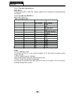
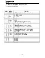
3-4-1 Function Description: Display the signal.
Pin No. SYMBOL
FUNCTION
1 DIAG_LOOP
Pin 1 & 34 must be connected together on the inverter board
2
VDD
Power Supply, 3.3 V (typical)
3
VDD
Power Supply, 3.3 V (typical)
4
V EEDID
DDC 3.3V power
5 NC
NC
6
Clk EEDID
DDC Clock
7 DATA
EEDID DDC
Data
8
Odd_Rin0-
- LVDS differential data input (R0-R5, G0) (odd pixels)
9
O
+ LVDS differential data input (R0-R5, G0) (odd pixels)
10
VSS
Ground – Shield
11
Odd_Rin1-
- LVDS differential data input (G1-G5, B0-B1) (odd pixels)
12
O
+ LVDS differential data input (G1-G5, B0-B1) (odd pixels)
13
VSS
Ground – Shield
14
Odd_Rin2-
- LVDS differential data input (B2-B5, HS, VS, DE) (odd pixels)
15
O
+ LVDS differential data input (B2-B5, HS, VS, DE) (odd pixels)
16
VSS
Ground – Shield
17
Odd_ClkIN-
- LVDS differential clock input (odd pixels)
18
Od
+ LVDS differential clock input (odd pixels)
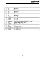
19 NC
NC
20 NC
No
connection
21
NC
No connection
22 NC
No
connection
23
NC
No connection
24 NC
No
connection
Содержание MSDV1636-O3
Страница 13: ...3 4 LED Panel 12 Service Manual Model No 316156WB111 CLAA156WB 11A ...
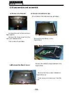
Страница 17: ... 0 4 5 Remove the power module Service Manual Model No 16 4 4 Remove the Main board take out the Power board ...
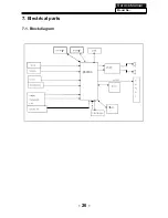
Страница 28: ...7 Electrical parts 7 1 Block diagram Service Manual Model No 26 06 ...
Страница 48: ...Service Manual Model No 46 9 Trouble shooting 9 1 Simple check ...
Страница 50: ...Service Manual Model No 48 3 Panel display abnormally connector j20 is at normal level ...
Страница 54: ...Service Manual Model No 52 7 PC no picture or picture abnormal ...
Страница 55: ...Service Manual Model No 8 YPBPR AV SCART no picture or picture abnormal Check Y 53 ...


