background image

- 15 -

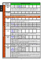
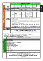
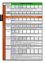
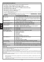
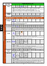
FUNCTIONS

NUMBER OF GREEN LED IMPULSES

1

2

3

4

5

6

7

8

NUMBER OF RED LED IMPULSES

10

Sound level

1 (MAX)

2

3

4

5

6

7

8 (MIN)

The values are relative to the sound level of both the Main Sound and the Alternative Sound. 

1

 is the 

Maximum

 and 

8

 is the 

Minimum

.

11

Maximum du-

ration of the 

sound in alarm 

status

1 minute

2 minutes

3 MINUTES

4 minutes

5 minutes

6 minutes

7 minutes

8 minutes

The values are relative to the sound level of both the Main Sound and the Alternative Sound.

12

Red LED and 

Green LED ca-

dence

STATUS

C a d e n c e 

similar to 

that  of  the 

FLASH

5   q u i c k 

flashes

1 impulse

5 quick flash

-

es at the un-

balancing and 

one impulse 

at  rebalanc

-

ing.

Red Led:

different 

frequency  

flashes.

Green Led: 

status

-

-

The value set is relative to both the functioning of the Red LED and that for the Green LED:

• 

Value 1

: the LEDs are activated with fixed light at the unbalancing of the relative input and deactivated 

at the rebalancing of the relative input

• 

Value 2

: the LEDs are activated with a cadence similar to that of the FLASH at the unbalancing of 

the relative input and deactivated at the rebalancing of the relative input

• 

Value 3

: the LEDs emit 5 quick flashes at the unbalancing of the relative input and deactivated at 

the rebalancing of the relative input 

• 

Value 4

: the LEDs are activated with fixed light for approximately one second at the unbalancing of 

the relative input and remain inhibited at the rebalancing of the relative input

• 

Value 5

: the LEDs emit 5 quick flashes at the unbalancing of the relative input and are activated with 

a fixed light for approximately one second at the rebalancing of the relative input

• 

Value 6

: the Red LED emit quick flashes at the unbalancing of the relative input and slowly at the 

rebalancing ; the FLASH emit few quick flashes at the unbalancing of STC and one slowly  

at the 

rebalancing; the Green LED is a “STATUS”

13

Anomalies and 

Tampers

See the “

Anomalies and Tampers memories

” table

The DEFAULT PARAMETERS are shown in 

BLUE BLOCK LETTERS

The Values selected are confirmed at the exit of the Programming Step

Signalling of Memories and Faults

• 

In step 13 of the Programming it is possible to see the details of the Fault and Tamper Memories. 

• 

More contemporary events are displayed one after another.

• 

Press the PB1 Button to delete the Fault and Tamper Memories.

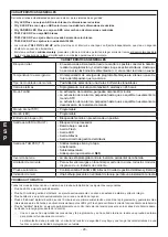
SIGNALLING FAULT AND TAMPER MEMORIES


(Signals visible at 

Step 13 of the Functions Table)


NUMBER OF GREEN LED IMPULSES

1

Siren battery low

2

Siren battery faulty

3

Not assigned

4

Anti-foam Probe input alarm (

optional

)

5

Thermal Probe Alarm 

6

Anti-perforation Probe Alarm

7

Lack of Power from the Control Unit

8

Cone management circuit fault

9

Cone fault

10

Flash fault

11

Accelerometer fault

12

Green LED fault

13

Red LED fault

The Anti-tear/Anti-opening Tamper Alarm is not signalled in the memory but only with the activation of the 

T T output

DURING THE VIEWING OF THE FAULT AND TAMPER MEMORIES 

IT IS POSSIBLE TO EXECUTE THE OVERALL DELETION BY PRESSING BUTTON PB1 

!!!WARNING!!! 

THE SIGNALLING WILL CONTINUE FOR THE FAULTS AND TAMPERS STILL PRESENT AFTER 

EXECUTING THE RESET

E

N

G

Содержание CITY CARB.LED HP

Страница 1: ...Italy www avselectronics com MANUALE GENERALE DI INSTALLAZIONE TS85 LED HP CITY LED HP I T A E N G F R A E S P SISTEMA DI QUALITA CERTIFICATO UNI EN ISO 9001 2008 Dispositivo omologato secondo la nor...

Страница 2: ...Comando sirena STC Programmabile Comando sirena LED Programmabile Ingresso di Blocco B Blocco del suono in presenza di un positivo Uscita di GUASTO FAULT Blocco microprocessore Batteria bassa o manca...

Страница 3: ...i 13 8 V NOTA al mancare dell alimentazione remota la sirena suona S1 Non usato J1 Connettore collegamento Cono e Batteria sirena J2 LED Connettore collegamento LED e FLASH J3 FOAM Connettore collegam...

Страница 4: ...di centraggio Leva del TAMPER Fori per il fissaggio del coperchio interno Utilizzare la dima o il fondo della sirena per predisporre i 3 fori di fissaggio a muro 1 2 e quello per il dispositivo Antiri...

Страница 5: ...ED VERDE vedi NUMERO IMPULSI LED VERDE nella Tabella Funzioni La visualizzazione viene ripetuta fino alla pressione di uno dei due pulsanti PB1 o PB2 utilizzare il tasto PB1 per modificare il valore d...

Страница 6: ...vr l ascolto della Modulazione 6 FLASH FLASH SEGUE STATO ALLARME FLASH di 40 minuti o ripristino da STC Ripristino da STC Valore 1 il Flash si ripristina al ribilanciamento dell ingresso che ha genera...

Страница 7: ...i allo sbilanciamento del relativo ingresso e si attivano con luce fissa per circa un secondo al ribilanciamento del relativo ingresso Valore 6 il LED Rosso emette lampeggi veloci allo sbilanciamento...

Страница 8: ...ntistrappo Zona 4 del satellite antischiuma Zona 5 del satellite sonda termica Zona 6 del satellite vibrazione accelerometro Zona 7 del satellite mancanza alimentazione da centrale Zona 8 del satellit...

Страница 9: ...0852V1 4 Curtarolo Padova Italy www avselectronics com GENERAL MANUAL FOR INSTALLATION TS85 LED HP CITY LED HP E N G CERTIFIED QUALITY SYSTEM UNI EN ISO 9001 2008 Device complies with EN50131 4 Certif...

Страница 10: ...rol input LED Programmable Block B Input Blocking of the sound in the presence of a positive FAILURE FAULT output Microprocessor block Low level or missing battery Flash fault LED fault Cone fault Con...

Страница 11: ...Cone and Siren Battery connection connector J2 LED LED and FLASH connection connector J3 FOAM Optional Anti foam connection connector S85 mode J4 TAMPER Anti removal system connection connector PB1 Pr...

Страница 12: ...main Centring turrets TAMPERING level Holes for fastening the internal cover Use the bottom of the siren to prepare the 3 holes used to fasten to the wall 1 2 and that for the Anti removal device 3 Us...

Страница 13: ...ng of the 8 possible values is shown by the flashing of the GREED LED see NUMBER OF GREEN IMPULSES in the Functions Table The displaying is repeated until one of the two buttons PB1 or PB2 is pressed...

Страница 14: ...M STATUS 40 minute FLASH or r e s t o r i n g from STC Restoring from STC Value 1 the Flash is restored at the rebalancing of the input that has generated the alarm Value 2 the Flash automatically de...

Страница 15: ...put Value 5 the LEDs emit 5 quick flashes at the unbalancing of the relative input and are activated with a fixed light for approximately one second at the rebalancing of the relative input Value 6 th...

Страница 16: ...ona 2 del satellite sum fault output reflects physical fault Extension Zona 3 del satellite input tamper Extension Zona 4 del satellite defoamers Extension Zona 5 del satellite thermal probe Extension...

Страница 17: ...4 Curtarolo Padova Italie www avselectronics com MANUEL G N RAL D INSTALLATION TS85 LED HP CITY LED HP SYST ME DE QUALIT CERTIFI UNI EN ISO 9001 2008 Appareil conforme la norme EN 50131 4 Grade 3 Cla...

Страница 18: ...sir ne Commande sir ne STC Programmable Commande LED Programmable Entr e de Blocage B Blocage du haut parleur l apparition d un positif Sortie PANNE DEFAUT Blocage microprocesseur Batterie faible ou...

Страница 19: ...ctivera la sir ne S1 Pas utilis J1 Connecteur branchement Haut Parleur et Batterie sir ne J2 LED Connecteur branchement LED et FLASH J3 FOAM Connecteur branchement sonde Antimousse optionnelle mod S85...

Страница 20: ...rous de centrage Levier du TAMPER Trous pour la fixation du cou vercle int rieur Dans le fond de la sir ne utiliser les 3 trous pour la fixation au mur 1 2 et le trou du dis positif de Protec tion ant...

Страница 21: ...la LED VERTE voir NOMBRE IMPULSIONS LED VERTE dans le Tableau Fonctions L affichage se r p te appuyer sur l un des boutons PB1 ou PB2 pour l arr ter utiliser le bouton PB1 pour modifier la valeur du p...

Страница 22: ...H SUIT L ALARME FLASH de 40 minutes ou r tablis sement de puis STC R tablisse ment depuis STC Valeur 1 le Flash se r tablit au r quilibrage de l entr e qui a g n r l alarme Valeur 2 le Flash se d sact...

Страница 23: ...ante et s allument pendant environ une seconde la d sactivation de celle ci Valeur 6 la LED Rouge met des clignotements rapides l activation de l entr e correspondante et des clignotements lents sa d...

Страница 24: ...uts refl te la sortie physique d faut Zone 3 du satellite entr e sabotage antiarrachage Zone 4 du satellite antimousses Zone 5 du satellite sonde thermique Zone 6 du satellite vibrations acc l rom tre...

Страница 25: ...4 Curtarolo Padova Italy www avselectronics com MANUAL GENERAL DE INSTALACI N TS85 LED HP CITY LED HP E S P SYST ME DE QUALIT CERTIFI UNI EN ISO 9001 2008 Dispositivo cumple con la norma EN 50131 4 Ce...

Страница 26: ...STC Programable Mando LED Programable Entrada de bloqueo B Bloqueo del sonido en presencia de un positivo Salida de AVER A FAULT Bloqueo microprocesador Bater a baja o ausente Aver a Flash Aver a LED...

Страница 27: ...suena S1 No utilizado J1 Conector conexi n Altavoz y Bater a sirena J2 LED Conector conexi n LED y FLASH J3 FOAM Conector conexi n sonda Antiespuma opcional mod S85 J4 TAMPER Conector conexi n sistema...

Страница 28: ...AM PER Orificios para fijar la tapa interior Utilice el fondo de la sirena para realizar los 3 orificios para la fijaci n en la pared 1 2 y l para el dis positivo Antides montaje 3 Utilice una punta d...

Страница 29: ...eos del LED VERDE v ase N MERO DE IMPULSOS DEL LED VERDE en la Tabla Funciones La visualizaci n se repite hasta que se pulse una de las dos teclas PB1 o PB2 utilice la tecla PB1 para modificar el valo...

Страница 30: ...POR E S T A D O ALARMA FLASH de 40 minutos o restauraci n desde STC Restaura ci n desde STC Valor 1 el Flash se restablece con el nuevo equilibrado de la entrada que ha generado la alarma Valor 2 el...

Страница 31: ...or 5 los LEDs emiten 5 parpadeos r pidos con el desequilibrio de la entrada correspondiente y se activan con luz fija durante aproximadamente un segundo con el nuevo equilibrado de la entrada correspo...

Страница 32: ...fleja salida f sica Zona 2 del sat lite Fallo suma salida refleja fallo f sico Zona 3 del sat lite entrada de tamper Zona 4 del sat lite antiespumantes Zona 5 del sat lite sonda t rmica Zona 6 del sat...

Отзывы: