- 12 -
E
N
G
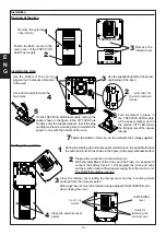
Installation
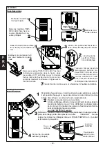
Opening of the siren
Installing the siren
Putting into operation
During the starting up and subsequent maintenance, it is possible to place
the outer and inner lid (as shown in the figure) to the polycarbonate bottom.
1
2
Prepare the connection to the control unit.
With the initial Block of the Cone and the Flash, it is possible to
connect the battery (max. 2.1 Ah) program the siren and carry
out the function tests without power supply from the control unit.
The TAMPER output is opened.
3
4
Close the internal cover letting the tamper level and the 4 centring turrets
protrude from the holes prepared.
!!Warning!! Do not crush the internal wiring cables (FOAM, TAMPER, etc.)
when closing the cover.
Close the external cover
(main)
C e n t r i n g
turrets
TAMPERING
level
Holes for
fastening the
internal cover
Use the bottom of the siren to
prepare the 3 holes used to fasten
to the wall...
1
2
...
and that for
the Anti-removal
device
3
Use an 8mm point to make the
four holes
Use the supplied bubble for the proper
positioning of the siren
4
5
On the TS85 P/V/X LED Plus models, remove the
spacer shown in the figure, in the CITY LED Plus
models, enter the supplied spacer, insert the plug
and tighten the screw making sure to maintain the
spacer in line with the bottom of the siren.
Fasten the bottom of the siren to the wall with the 3 plugs supplied
6
Turn the tamper in place, in
the TS85 P/V/X LED models,
at the spacer tamper and in
the version CITY LED Plusto
the fixing screw of the spacer
tamper.
7
Remove the external
cover (main)
Fasten the flash covers to the
main cover of the TS85 P/V/X
LED Plus models
2
1
3
Remove the
internal cover
TS85 P/V/X LED
CITY PLUS LED

