background image

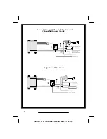
Tach Wire (RPM Monitoring)

The AviStart is designed to monitor the vehicle RPM by connecting directly to
the vehicle tachometer wire which is usually located at the distributor,
ignition coil or diagnostic plug. On most vehicles, the tach wire is easily
accessible. If the tach wire is not accessible, there are several alternative
choices.  Contact Avital Technical Support Department for alternate choices.

The following procedure for testing the vehicle tach wire is not exact and may 
vary with different vehicle make, model and year. We recommend that you
refer to your AviFax documents for tach color code and location information.

1 . Set your voltmeter to the AC voltage scale.
2 . Start the vehicle. Use the voltmeter to find a wire that will show 1 to 5

volts AC while the vehicle is idle and increase an additional 1 to 5 volts
AC when the engine RPM is raised to 3000-4000 RPM.

3. Connect the 

WHITE/GREEN 

wire to the vehicle tach wire.

Hood Switch (Mandatory)

As a safety precaution, the hood switch prevents the vehicle from starting
when the hood is open. If the vehicle is in the remote start mode and the hood 
is opened, the remote start will immediately shut down. The hood switch will
also trigger the alarm when opened.

1. Choose a location under the hood away from direct exposure to water or

water drain areas.

2 . Check for proper hood clearance.
3 . Make sure the hood switch will make contact with a flat surface on the

hood when closed.

4 . Drill a 

5

/

16

" mounting hole.

5. Mount the hood switch.
6 . Connect the 

TAN

 wire to the hood switch.

7. Make sure the hood makes contact with hood switch when closed and

presses the hood switch straight down to prevent wear.

13

AviStart 2501 Installation Manual - Rev. B 100199

Содержание AviStart 2501

Страница 1: ...AviStart 2501 Installation Manual Rev B 100199 ...

Страница 2: ...AviStart 2501 Installation Manual Rev B 100199 ...

Страница 3: ...Parking Lights 6 Glow Plug Light Input 6 Reverse Light 7 Remote Start Activated Output 7 Factory Alarm Disarm Output 7 Factory Alarm Rearm 8 Ignition Switch Connections 8 Remote Engine Start Neutral Safety Switch Bulletin 1 0 Tach Wire RPM Monitoring 1 3 Hood Switch Mandatory 1 3 Power and Ground Connections 1 4 Mandatory RPM Programming 1 4 Programmable Features 1 5 Programming Table for System F...

Страница 4: ...ires from the control unit directly to the battery 4 Keep extensions as short as possible Use same gauge wires for short extensions and larger gauge wires for longer extensions 5 DO NOT disconnect the battery cables Make all connections by removing the bolts from the cable clamps without detaching the clamp 6 Turn off dome light or remove dome light fuse to prevent battery drain This device compli...

Страница 5: ...3 AviStart 2501 Installation Manual Rev B 100199 Main Wiring Diagram ...

Страница 6: ...W BLACK Reverse Light Input 9 TAN Hood Switch Input 10 RED BLACK Parking Light Output 11 GRAY BLACK Remote Start Activated Output 12 GRAY WHITE Factory Alarm Disarm Output 13 RED WHITE Parking Light Polarity Input or Select 14 RED Battery 6 Pin Connector Pin Number Wire Color Description 1 PINK Ignition Output 2 RED Battery 12 Volts 3 PINK Ignition Output 4 VIOLET Starter Output 5 GRAY Heater AC O...

Страница 7: ... control unit as possible 3 Route the antenna cable up through the driver side windshield pillar behind the headliner and behind the rear view mirror 4 Fasten the antenna to the windshield with the attached adhesive tape Attach the antenna vertically so the rubber tip on the end of the antenna is facing downward Wireloom 1 Plug the wirelooms securely into the control unit 2 Route wires from the co...

Страница 8: ...e a voltmeter to find the one wire at the brake light switch usually located on the upper brake pedal arm that shows 12 volts when you press the brake pedal and 0 volts when the brake pedal is not pressed 3 Connect the YELLOW wire to the vehicle brake light switch wire Parking Lights 1 If the parking lights are positive trigger connect the RED WHITE wire to the battery positive terminal through th...

Страница 9: ...k while in the remote start mode the system will shut down immediately 1 Set the parking brake 2 Turn the ignition key to the ON position and adjust the gear shift selector to Reverse 3 Use a voltmeter to find the wire that will show 12 volts in Reverse and 0 volts in Park 4 Connect the YELLOW BLACK wire to the vehicle s reverse light wire Remote Start Activated Output The GRAY BLACK wire will pro...

Страница 10: ...tem does not have a designated arm wire To arm the alarm you must lock the doors while the interior lights are on 1 Use a volt ohmmeter to locate the vehicle lock switch wire If the vehicle lock wire is not trigger you will need to add a relay 2 Connect the AviStart BLUE WHITE wire to the vehicle lock wire or additional lock relay 3 Use a volt ohmmeter to find the vehicle interior light wire It wi...

Страница 11: ...activate the vehicle s heater AC system an additional 30 amp relay must be added Do not use the GRAY wire to power more than one heater AC wire 1 Use a voltmeter to find the wire s that show 12 volts when the ignition key is in the ON position 0 volts while the starter is cranking and 12 volts while running 2 Cut this wire in half Start the vehicle and turn the blower switch on The blower should n...

Страница 12: ...ome vehicles combine the neutral safety switch and the steering column shift mechanism together The starter wires run from the combined switch directly to the starter solenoid The remote start wire connection cannot be made between the ignition switch and the neutral safety switch As a result if the vehicle was left in gear with the key in the ignition and not in the locked position the vehicle co...

Страница 13: ...ges 5 Activate the remote engine starter 6 If the vehicle starter engages immediately press the brake pedal to disengage shut down the remote start You have a combined type neutral safety switch and you will have to add an additional relay as shown in the diagram 7 If the vehicle starter does not engage no additional relays are required All vehicles have a key in the ignition reminder circuit key ...

Страница 14: ...12 AviStart 2501 Installation Manual Rev B 100199 Gen eral Mo tors Sport Util ity Ve hi cles Trucks and ColumnShiftPassengerVehicles DodgeDakotaPickupTrucks ...

Страница 15: ...volts AC while the vehicle is idle and increase an additional 1 to 5 volts AC when the engine RPM is raised to 3000 4000 RPM 3 Connect the WHITE GREEN wire to the vehicle tach wire Hood Switch Mandatory As a safety precaution the hood switch prevents the vehicle from starting when the hood is open If the vehicle is in the remote start mode and the hood is opened the remote start will immediately s...

Страница 16: ...ected correctly 11 Install the 5 amp fuse in the 18 ga RED wire fuse assembly 12 Install the 20 amp fuse in theRED WHITE wire fuse assembly 13 Install the two 20 amp fuses in the 10 ga RED wire fuse assemblies Mandatory RPM Programming In order to remote start the vehicle engine and prevent over grinding of the starter motor the engine RPM must be programmed into the system memory The AviStart has...

Страница 17: ...ode 2 Select the feature you wish to program from the Programming Table for System Features or the Programming Table for Remote Controls on page 16 Note the number of beeps associated with that feature 3 Turn the ignition key to the ON position 4 Within 10 seconds begin flicking the valet switch on and off The piezo beeper will beep once each time you flick the switch on then off 5 Continue flicki...

Страница 18: ... Factory Setting No of beeps Secondary Action Remote Engine Start Green START Button 6 Press the Green START Button the piezo beeper will beep 1 times Remote Engine Stop Red STOP Button 7 Press the Red STOP Button the piezo beeper will beep 2 times One Step Remote Control Code Learning Green START Button 8 Press the Green START Button the piezo beeper will beep 1 time Instant Remote Control Code D...

Страница 19: ...17 AviStart 2501 Installation Manual Rev B 100199 ...

Страница 20: ...AviStart 2501 Installation Manual Rev B 100199 1999 Avital Technologies Inc A Division of Clifford Electronics PartNumber 32 2501B AviStart2501IM 1099 ...

Отзывы: