


Installation Procedures
Control Unit
1 . Select a location under the dash that will allow you to use the tie wraps to
securely fasten the control unit.
2 . Mount the control unit as high as possible to ensure maximum security.
3 . Do not mount the control unit near moving parts.
4 . Avoid areas that are in the direct path of air blowing from the vents.
5 . Route wires from this point, leaving slack for ease of service.
RangeMaster™ Super Heterodyne Receiver Module
1 . Plug the receiver module
WHITE
connector into the control unit
WHITE
plug.
2. Use tie wraps to fasten the receiver module as far from the control unit as
possible.
3 . Route the antenna cable up through the driver side windshield pillar,
behind the headliner and behind the rear view mirror.
4 . Fasten the antenna to the windshield with the attached adhesive tape.
Attach the antenna vertically so the rubber tip on the end of the antenna is
facing downward.
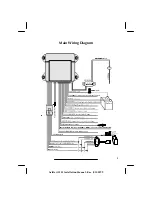
Wireloom
1. Plug the wirelooms securely into the control unit.
2. Route wires from the control module directly to each connection point.
3 . Separate the small and large
RED
,
RED/WHITE
,
BLACK
,
TAN
, and
WHITE/GREEN
wires.
4. Sleeve these wires with vinyl tubing or electrical tape and route them
through an existing rubber grommet into the engine compartment.
5 . If an existing grommet is not available, drill a hole and install a snap
grommet.
5
AviStart 2501 Installation Manual - Rev. B 100199


