


Drive (CDM) Design
T1689 Technical Manual Rev 07
Component Selection – Electrical
MV3000 Air Cooled DELTA
Page 98
3.8.6.3
Pre-Charge System Components
NOTE:
All components are system dependant and must be specified and sourced per application.
•
Pre-charge resistors (multiple components in series/parallel to provide the correct rating per
phase) and mounting kits.
•
Pre-charge contactor and suppression components.
•
Pre-charge fuses and mounting kits.
•
Power connections between supply, fuses, pre-charge resistors, pre-charge contactor and main
supply reactor.
•
Control electrical connections to the controller for the pre-charge contactor and main supply
contactor.
3.8.6.4
Pre-Charge System Electrical Details
•
Pre-charge current is typically 30 to 50% of drive rating. DELTA module capacitor bank details are
given in the individual component specification.
•
Pre-charging energy levels need to be considered due to the impulse nature of the pre-charging
event.
•
When sizing pre-charge components, consider all items to be pre-charged (DELTA modules, DB
units, SMPS’s).
•
In multiple parallel network DELTA systems, pre-charging can be done through one DELTA
module only.
•
The control connections are as follows:
•
The “pre-charge complete” signal is generated by the controller and must be used to close
the main supply contactor.
•
The “pre-charge acknowledge” signal from the main contactor back to the controller
confirms correct operation and interlocks the sequence to prevent the drive from starting
if not complete.
•
The pre-charge circuit must be opened at the end of the pre-charging period to prevent
circulating currents.
•
Controller connections are detailed in Section 2: Specification.
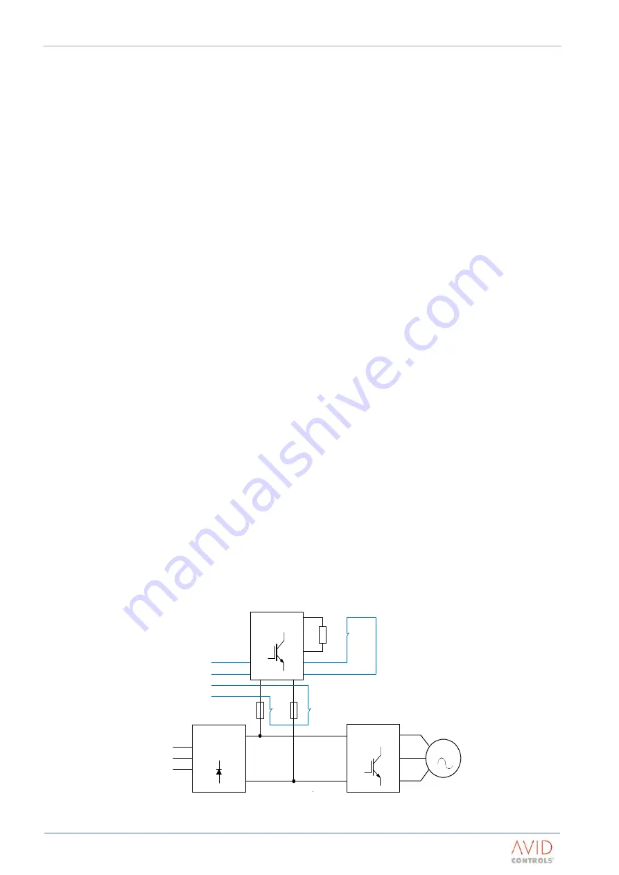
3.8.7
Dynamic Braking (DB) Units
The DB Unit is used in conjunction with an externally mounted braking resistor, to dissipate kinetic energy
stored in a motor and its load or to assist in limiting transient voltages. The kinetic energy is regenerated into
the drive during deceleration or when the load is overhauling. The DB monitors the DC link voltage and
switches the braking resistor into circuit when the voltage exceeds a pre-set level.
MOTOR
Machine Bridge
-
Network Bridge
+
Dynamic Brake
To
Control
Braking
Resistor
Thermal
Protection
Θ
Main a.c.
Supply
Figure 3–9. – DB System Arrangement
Содержание MV3000 DELTA
Страница 1: ...T1689 Technical Manual Rev 07 MV3000 Air Cooled DELTA...
Страница 150: ...Maintenance T1689 Technical Manual Rev 07 Capacitor Reforming MV3000 Air Cooled DELTA Page 150 Page Intentionally Blank...
Страница 152: ...T1689 Technical Manual Rev 07 MV3000 Air Cooled DELTA Page 152 Page Intentionally Blank...
Страница 184: ...T1689 Technical Manual Rev 07 MV3000 Air Cooled DELTA Page 184 Page Intentionally Blank...


