background image

3

English

Safety Rules

4

Specifications

Tool Specification

5

Tool Dimensions

5

Intent of Use

Range of Fasteners

6

Part Numbering

6

Putting into Service

Air Supply

7

Operating Procedure

7

Adjusting Vacuum Extraction

7

Nose Assemblies

Nose Tips

8-10

Fitting Instructions

9

Fitting Instructions for Maxlok

®

and Avtainer

®

11

Servicing Instructions for all nose assemblies

11

Accessories

Stem Deflector

12

Extension

12

Side Ejector

12

Servicing the Tool

Daily / Weekly

13

Moly Lithium Grease EP 3753 Safety Data

13

MolyKote 55m & MolyKote 111 Safety Data

14

Annually

15

Service Kit

15

Head Assembly

15-16

Pneumatic Piston Assembly

16

Valve Spool Assembly

16

Trigger

16

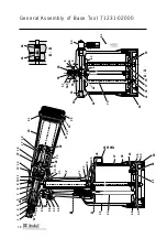
General Assembly of Base Tool

General Assembly and Parts List

18-19

Priming

Oil Details

20

Hyspin VG 32 Safety Data

20

Priming Kit

20

Priming Procedure

21

Fault Diagnosis

Symptom, Possible Cause & Remedy

22-23

Français

25

Deutsch

47

Italiano

69

Avdel UK Limited

policy is one of continuous product development and improvement and we reserve the right to change the specification of any product without prior notice.

Warranty

Avdel installation tools carry a 12 month warranty against defects caused by faulty

materials or workmanship, the warranty period commencing from the date of delivery

confirmed by invoice or delivery note.

The warranty applies to the user/purchaser when sold through an authorised outlet,
and only when used for the intended purpose. The warranty is invalidated if the
installation tool is not serviced, maintained and operated according to the instructions
contained in the Instruction and Service Manuals.

In the event of a defect or failure, and at its sole discretion, Avdel undertakes only to
repair or replace faulty components.

Contents

Содержание Genesis G4 HD

Страница 1: ...vy Duty Attrezzo oleopneumatico Genesis G4 HD Maggiorato Hydro Pneumatic Power Tool Genesis G4 HD Heavy Duty Outil ol o pneumatique Genesis G4 HD Haut rendement Instruction Manual Manuel d instruction...

Страница 2: ......

Страница 3: ...G 32 Safety Data 20 Priming Kit 20 Priming Procedure 21 Fault Diagnosis Symptom Possible Cause Remedy 22 23 Fran ais 25 Deutsch 47 Italiano 69 Avdel UK Limited policy is one of continuous product deve...

Страница 4: ...assembly 8 Do not operate a tool machine that is directed towards any person s or the operator 9 Always adopt a firm footing or a stable position before operating the tool machine 10 Ensure that vent...

Страница 5: ...01 5 psi Free Air Volume Required 5 5 bar 4 3 litres 0 15 cuft Stroke Minimum 17 mm 0 7 in Pull Force 5 5 bar 18 68 kN 4200 lbf Cycle time Approximately 1 2 seconds Noise Level 75 dB A Weight Without...

Страница 6: ...4 3 4 8 5 5 2 6 6 4 6 5 7 8 9 9 5 10 3 16 1 4 3 8 COMPLETE TOOL 71231 00 BASE TOOL 1 1 2 3 1 NOSE ASSEMBLY NOSE TIP 2 71231 02000 71210 15000 see note 3 2 3 3 4 4 The part number of the base tool rema...

Страница 7: ...CEPT AVTAINER AND MAXLOK Ensure that a nose assembly suitable for the fastener is fitted see pages 8 10 Connect the tool to the air supply Insert the fastener stem into the nose of the tool The fasten...

Страница 8: ...el4 Al Steel4 3 16 3 16 3 16 3 16 1 4 3 16 3 16 3 16 3 16 1 4 3 16 3 16 1 4 3 16 3 16 3 16 3 16 1 4 3 16 3 16 3 16 1 4 3 16 1 4 3 16 3 16 3 16 3 16 1 4 1 4 1 4 1 4 2 8 3 3 3 3 4 1 3 3 3 3 2 8 2 8 2 8...

Страница 9: ...A B TYPE 2 NOSE TIPS ARE EXTENDED TO ALLOW ACCESS INTO APPLICATIONS WHERE TYPE 1 NOSE TIPS WILL NOT REACH T Y P E 2 N O S E T I P S 8 7 6 5 4 2 3 1 58 3 22 9 T Y P E 3 N O S E T I P S COMPLETE TOOL P...

Страница 10: ...G GUIDE 07220 02104 7 SPRING 07610 02107 8 LOCKING RING 07610 02004 12 ANVIL 07610 02001 ITEM DESCRIPTION PART N 9 CHUCK COLLET 07610 02102 4 JAWS 07610 02103 10 SPRING GUIDE 07220 02104 7 SPRING 0761...

Страница 11: ...1 O ring 2 and vacuum tube 51 Substitute jaw spreader housing 1 with chuck collet adaptor 07610 00501 Tighten fully onto piston before tightening the locknut against it Fit locking ring 8 onto the chu...

Страница 12: ...for fasteners with a stem larger than 3 1 mm 1 8 STEM DIAMETER Fitted between the tool and the nose assembly the extension gives an extra reach of 76 millimetres ideal for use in deep narrow applicati...

Страница 13: ...k see Operating Procedure page 7 Dismantle and clean nose assembly with special attention to the jaws Lubricate with Moly Lithium grease EP 3753 before assembling Check for air leaks Grease can be ord...

Страница 14: ...the aquatic environment However due to the physical form and water insolubility of the product the bioavailability is negligible Handling General ventilation is recommended Avoid skin and eye contact...

Страница 15: ...70 Loosen locknut 3 with a spanner then unscrew jaw spreader housing 1 and O ring 2 Remove locknut 3 together with O rings 49 and 50 Push head piston 7 to the rear and out of head assembly 4 taking ca...

Страница 16: ...ith O ring 39 lip seal 41 3 off and guide ring 35 Assemble in reverse order Remove pneumatic piston assembly 42 and seal assembly 34 as described immediately above Using the T spanner and T spanner sp...

Страница 17: ...17 English Notes...

Страница 18: ...65 37 84 85 86 87 38 40 39 83 31 33 34 A A 44 45 36 35 B B 1 2 3 4 9 10 5 8 31 30 32 46 48 67 47 51 50 49 26 73 70 28 72 16 17 18 14 20 21 22 25 24 11 7 A 23 13 88 42 41 80 82 81 A A 6 64 59 58 57 54...

Страница 19: ...53 54 55 56 57 58 59 60 61 62 63 64 65 66 67 68 69 70 72 73 74 75 76 77 78 79 80 81 82 83 84 85 86 87 88 71210 02008 71210 02024 07003 00310 07003 00204 71230 02102 07003 00127 07005 01274 71210 03400...

Страница 20: ...07992 00006 Please see safety data below First Aid SKIN Wash thoroughly with soap and water as soon as possible Casual contact requires no immediate attention Short term contact requires no immediate...

Страница 21: ...w spreader housing 1 Disconnect air supply to tool or switch ON OFF valve 60 to OFF position Fill the priming pump with oil Screw priming pump 07900 00700 into the bleed screw hole with seal 10 in pla...

Страница 22: ...ghten joints or replace components Low oil level or air present in oil Prime tool 20 21 Cannot feed next Broken stems jammed inside tool Empty stem collector 4 point 14 fastener Check jaw spreader is...

Страница 23: ...andards EN292 part 1 and part 2 ISO 8662 part 1 EN 60742 0695 ISO 3744 EN 50081 1 ISO PREN792 part 14 EN 55014 following the provisions of the Machine Directive 89 392 EC as amended by Directive 91 36...

Страница 24: ......

Страница 25: ...iste de pi ces 40 41 Plein d huile Huile recommand e 42 Informations de s curit huile Hyspin VG 32 42 Kit de plein d huile 42 Proc dure de plein d huile 43 Diagnostic des pannes Sympt me cause possibl...

Страница 26: ...u d montage d un ensemble de nez 8 Ne pas actionner un outil une machine orient s vers une des personne s ou l op rateur 9 L op rateur veillera adopter une position quilibr e et stable avant d utilise...

Страница 27: ...5 7 bars Volume d air libre n cessaire 5 5 bars 4 3 litres Course Minimum 17 mm Force de traction 5 5 bars 18 68 kN Cycle de pose Approximativement 1 2 secondes Niveau sonore 75 dB A Poids Sans quipem...

Страница 28: ...C LC AVSEAL QTM RIVET TTM RIVET CHERRYMATETM 4 3 4 8 5 5 2 6 6 4 6 5 7 8 9 9 5 10 3 16 1 4 3 8 OUTIL COMPLET 71231 00 OUTIL DE BASE 1 1 2 3 1 ENSEMBLE DE NEZ NEZ 2 71231 02000 71210 15000 voir note 3...

Страница 29: ...EGULATOR AND FILTER DRAIN DAILY 3 METRES MAXIMUM 4 TOUTES FIXATIONS SAUF AVTAINER ET MAXLOK V rifier que l ensemble de nez mont correspond la fixation poser voir pages 30 32 Raccorder l outil l alimen...

Страница 30: ...l Steel4 Al Al4 Al Al4 Al Steel4 Al Steel4 3 16 3 16 3 16 3 16 1 4 3 16 3 16 3 16 3 16 1 4 3 16 3 16 1 4 3 16 3 16 3 16 3 16 1 4 3 16 3 16 3 16 1 4 3 16 1 4 3 16 3 16 3 16 3 16 1 4 1 4 1 4 1 4 2 8 3 3...

Страница 31: ...ERENCE 1 07340 02804 2 07003 00067 3 07340 00304 4 71210 15001 5 07498 04502 6 71210 05001 7 07500 00418 8 07340 00327 CARTER DE NEZ JOINT TORIQUE CARTER PORTE MACHOIRES MACHOIRES PORTE MACHOIRES BUTO...

Страница 32: ...SCRIPTIONREFERENCE 9 07610 02102 4 07610 02103 10 07220 02104 7 07610 02107 8 07610 02004 12 07610 02101 LES TROIS COMPOSANTS ILLUSTRES CI CONTRE SONT INDISPENSABLES POUR MONTER UN ENSEMBLE DE NEZ MAX...

Страница 33: ...ter guide 1 le joint torique 2 et le tube de d pression 51 Remplacer le carter guide 1 par l adaptateur de bo tier de mors 07610 00501 Serrer fond sur le piston puis serrer l crou de blocage contre lu...

Страница 34: ...our diam tre de tige sup rieur 3 1 mm DIAMETRE DE LA TIGE Mont e entre l outil et l ensemble de nez la rallonge donne l outil une port e suppl mentaire de 76 mm qui convient aux applications profondes...

Страница 35: ...ir proc dure op ratoire page 29 D monter et nettoyer l ensemble de nez en pr tant une attention particuli re aux m choires Lubrifier la graisse au bisulfure de molybd ne avant de remonter S assurer de...

Страница 36: ...ysique et l insolvabilit dans l eau du produit rendent sa biodisponibilit n gligeable Manutention A ration g n rale recommand e Eviter tout contact avec la peau ou les yeux Stockage Ne pas stocker pro...

Страница 37: ...2 Enlever l crou de blocage 3 avec les joints toriques 49 et 50 Pousser le piston de t te 7 vers l arri re et le d gager de l ensemble t te 4 en veillant ne pas endommager l al sage du cylindre Enlev...

Страница 38: ...d montage Enlever l ensemble piston pneumatique 42 et l ensemble d tanch it 34 de la fa on d crite imm diatement ci dessus Avec la cl en T et son embout desserrer l crou de blocage 36 et l enlever ave...

Страница 39: ...39 Fran ais Notes...

Страница 40: ...66 65 37 84 85 86 87 38 40 39 83 31 33 34 A A 44 45 36 35 B B 1 2 3 4 9 10 5 8 31 30 32 46 48 67 47 51 50 49 26 73 70 28 72 16 17 18 14 20 21 22 25 24 11 7 A 23 13 88 42 41 80 82 81 A A 6 64 59 58 57...

Страница 41: ...ON QTE RECHANGE REPERE REFERENCE DESCRIPTION QTE RECHANGE CARTER GUIDE JOINT TORIQUE ECROU DE BLOCAGE ENSEMBLE TETE LOGEMENT DE JOINT JOINT TORIQUE PISTON DE TETE JOINT A LEVRE VIS JOINT COLLE JOINT A...

Страница 42: ...informations de s curit ci dessous Premiers secours PEAU Laver soigneusement l eau et au savon d s que possible Un contact occasionnel ne requiert pas de soins imm diats Un contact de courte dur e ne...

Страница 43: ...pneumatique de l outil ou mettre la valve de marche arr t 60 sur OFF Remplir la pompe d huile Visser la pompe de plein d huile 07900 00700 sur l orifice de la vis de purge avec le joint 10 en place A...

Страница 44: ...r la pression d air la valeur recommand e Utiliser l outil genesis plus puissant Prendre contact avec Avdel UK Limited Faire le plein d huile Choisir la bonne longueur R gler la pression d air la vale...

Страница 45: ...parties 1 et 2 ISO 8662 partie 1 EN 60742 0695 ISO 3744 EN 50081 1 ISO PREN792 partie 14 EN 55014 suivant les dispositions de la Directive sur les machines 89 392 CE modifi e par la Directive 91 368...

Страница 46: ......

Страница 47: ...ff llsatz 64 Auff llvorgang 65 Beseitigen von St rungen Symptom m gliche Ursache und Abhilfe 66 67 Im Rahmen der Gesch ftspolitik der st ndigen Produktentwicklung und verbesserung beh lt sich Avdel UK...

Страница 48: ...s sie auf Personen oder den Bediener gerichtet ist 9 Vor dem Betrieb des Ger tes der Maschine immer eine standfeste Position einnehmen 10 Sicherstellen dass die Entl ftungsl cher nicht verstopft oder...

Страница 49: ...101 5 psi Erforderliches Luftvolumen bei 5 5 bar 4 3 Liter 0 15 ft3 Hub Minimum 17 mm 0 7 Zoll Zugkraft bei 5 5 bar 18 68 kN 4200 lbf Taktzeit ca 1 2 Sekunden Arbeitsger usch 75 dB A Gewicht ohne Aus...

Страница 50: ...2 3 1 AUSR STUNG MUNDST CK 2 71231 02000 71210 15000 siehe Hinweis 3 2 3 3 3 ZIFFERN AUS DER LETZTEN SPALTE DER MUNDST CK TABELLE AUF SEITE 52 53 ODER 54 ZUGEBEN F R MAXLOK DIE MAXLOK TABELLE AUF SEI...

Страница 51: ...r das Niet geeignete komplette Ausr stung eingebaut ist siehe Seite 52 54 Das Ger t an die Druckluftversorgung anschlie en Den Dorn des Niets in das Mundst ck des Ger tes legen Der Niet wird mit Hilfe...

Страница 52: ...4 1 4 1 4 1 4 2 8 3 3 3 3 4 1 3 3 3 3 2 8 2 8 2 8 2 8 2 8 5 5 7 3 5 6 7 3 5 6 7 3 4 1 4 4 4 8 3 3 3 3 4 8 3 3 5 7 3 3 5 7 2 8 3 3 3 3 3 3 3 3 9 5 8 0 9 5 9 0 11 2 8 0 10 2 8 3 12 7 19 0 12 7 12 7 12...

Страница 53: ...EN VERL NGERT UM ZUGANG ZU DEN ANWENDUNGEN ZU ERLAUBEN DIE F R MUNDST CKE TYP 1 AUSSER REICHWEITE SIND KOMPLETTES GER T TEILNUMMER mit 71231 00 vorangehend MUNDST CKH LSE O RING SPANNBACKENPATRONE SPA...

Страница 54: ...00 4 8 6 4 MAXLOK 371 372 8 7 10 9 4 10 64 5 19 M A X L O K O H N E M U N D S T C K Art Nr 07610 02000 3 1 6 A U S R S T U N G A U S R S T U N G Art Nr 07610 02100 1 4 1 Zuerst in Zoll dann in mm NIET...

Страница 55: ...e 54 F hrungsbuchse 1 O Ring 2 und Absaugungsrohr 51 entfernen Die F hrungsbuchse 1 durch den Spannbackenpatronenadapter 07610 00501 ersetzen Vor dem Anziehen der Kontermutter auf dem Kolben fest anzi...

Страница 56: ...mm Durchmesser DORNDURCHMESSER Durch die zwischen dem Ger t und der kompletten Ausr stung angebrachte Verl ngerung erh lt man eine zus tzliche Reichweite von 76 mm die ideal bei der Verwendung in tief...

Страница 57: ...Betrieb auf Seite 51 Ausr stung demontieren und reinigen dabei besonders die Spannbacken beachten Vor der Montage mit Molylithiumfett EP 3753 schmieren Auf Luftleckagen berpr fen Fett kann separat bes...

Страница 58: ...asserunl slichkeit des Produkts ist die Bioverf gbarkeit vernachl ssigbar Handhabung Eine allgemeine Arbeitsplatzbel ftung wird empfohlen Haut und Augenkontakt vermeiden Lagerung Nicht zusammen mit ox...

Страница 59: ...chl ssel lockern Dann F hrungsbuchse 1 und O Ring 2 abschrauben Kontermutter 3 zusammen mit O Ringen 49 und 50 entfernen Kopfkolben 7 nach hinten aus dem Kopf 4 dr cken Dabei darauf achten dass die Zy...

Страница 60: ...ung 41 3 St ck und F hrungsring 35 entfernen Zusammenbau erfolgt in umgekehrter Reihenfolge Druckluftkolben 42 und Dichtung 34 wie unmittelbar vorstehend beschrieben ausbauen Mit Hilfe des Steckschl s...

Страница 61: ...61 Deutsch Anmerkungen...

Страница 62: ...66 65 37 84 85 86 87 38 40 39 83 31 33 34 A A 44 45 36 35 B B 1 2 3 4 9 10 5 8 31 30 32 46 48 67 47 51 50 49 26 73 70 28 72 16 17 18 14 20 21 22 25 24 11 7 A 23 13 88 42 41 80 82 81 A A 6 64 59 58 57...

Страница 63: ...2 1 1 1 1 1 47 48 49 50 51 52 53 54 55 56 57 58 59 60 61 62 63 64 65 66 67 68 69 70 72 73 74 75 76 77 78 79 80 81 82 83 84 85 86 87 88 71210 02008 71210 02024 07003 00310 07003 00204 71230 02102 07003...

Страница 64: ...n Erste Hilfe HAUT Sobald wie m glich gr ndlich mit Seife und Wasser waschen Ein zuf lliger Kontakt erfordert keine sofortigen Ma nahmen Ein kurzzeitiger Kontakt erfordert keine sofortigen Ma nahmen E...

Страница 65: ...IST Haltemutter 07900 00698 auf F hrungsbuchse 1 aufschrauben Druckluftversorgung zum Ger t abtrennen oder Schieber EIN AUS 60 auf Position AUS schieben Die lpresse mit l auff llen lpresse 07900 00700...

Страница 66: ...leistungsf higeres Genesis Ger t verwenden Avdel UK Limited kontaktieren Ger t mit l auff llen Auf korrekte L nge umstellen Luftdruck auf vorgeschriebenen Wert einstellen Ersetzen Ger t mit l auff ll...

Страница 67: ...rung bezogen ist den nachstehenden Normen entspricht EN292 Teil 1 und Teil 2 ISO 8662 Teil 1 EN 60742 0695 ISO 3744 EN 50081 1 ISO PREN792 Teil 14 EN 55014 in Befolgung der Vorschriften der Maschinen...

Страница 68: ......

Страница 69: ...l olio Caratteristiche olio 86 Scheda di sicurezza olio Hyspin VG 32 86 Corredo per il rabbocco 86 Procedura di rabbocco 87 Individuazione guasti Sintomi cause possibili e rimedi 88 89 Avdel UK Limite...

Страница 70: ...all attacco di ingresso dell attrezzo macchina prima di regolare montare o smontare la testata 8 Non puntare l attrezzo macchina verso l operatore o altre persone che si trovino in vicinanza 9 Trovare...

Страница 71: ...e aria minima massima 5 7 bar Volume richiesto aria libera 5 5 bar 4 3 litri Corsa minima 17 mm Forza di trazione 5 5 bar 18 68 kN Tempo ciclo circa 1 2 secondi Rumorosit 75 dB A Peso Senza testata 2...

Страница 72: ...2 3 1 TESTATA NASELLO 2 71231 02000 71210 15000 vedere spiegazione 3 2 3 3 INSERIRE LE TRE CIFRE CHE APPAIONO NELL ULTIMA COLONNA DELLE TABELLE DEI NASELLI A PAGINA 74 75 E 76 PER TESTATE MAXLOK CONSU...

Страница 73: ...IONE PRINCIPALE REGOLATORE DI PRESSIONE E FILTRO SPURGARE GIORNALMENTE 3 METRI MASSIMO 4 TUTTI I TIPI DI RIVETTI ECCETTO AVTAINER E MAXLOK Assicurarsi di aver montato la testata adatta vedere pagine 7...

Страница 74: ...3 3 4 1 3 3 3 3 2 8 2 8 2 8 2 8 2 8 5 5 7 3 5 6 7 3 5 6 7 3 4 1 4 4 4 8 3 3 3 3 4 8 3 3 5 7 3 3 5 7 2 8 3 3 3 3 3 3 3 3 9 5 8 0 9 5 9 0 11 2 8 0 10 2 8 3 12 7 19 0 12 7 12 7 12 7 19 0 12 7 12 7 12 7 1...

Страница 75: ...ERNO O RING SEDE GANASCE GANASCE DIVARICATORE GANASCE PARACOLPI MOLLA ANELLO DI BLOCCAGGIO I NASELLI TIPO 2 SONO ALLUNGATI PER PERMETTERE ACCESSO ALLE APPLICAZIONI CHE I NASELLI 1 NON POSSONO RAGGIUNG...

Страница 76: ...00 4 8 6 4 MAXLOK 3 7 1 3 7 2 8 7 10 9 4 10 64 5 19 CODICE ATTREZZO COMPLETO preceduto da 71231 00 M A X L O K S E N Z A N A S E L L O R I V E T T O MATERIALE 1 T E S T A T A vedi sotto CODICE TIPO 1...

Страница 77: ...tubo depressione 51 Montare al posto della sede divaricatore ganasce 1 il raccordo del canotto interno 07610 00501 Avvitarlo a fondo sul pistone prima di stringere su di esso il controdado Montare l a...

Страница 78: ...ggiore di 3 1 mm 1 8 pollici DIAMETRO GAMBO La prolunga montata tra l attrezzo e la testata aumenta il raggio d azione dell attrezzo di 76 millimetri favorendo il raggiungimento di punti situati in pr...

Страница 79: ...ontare e pulire la testata facendo attenzione particolare alle ganasce Lubrificare con grasso al molitio EP 3753 prima di montare Controllare che non ci siano perdite d aria Il grasso pu essere ordina...

Страница 80: ...isica e dell insolubilit in acqua del prodotto la biodisponibilit trascurabile Maneggiamento Si raccomanda di ventilare l ambiente Evitare il contatto con la pelle e con gli occhi Immagazzinaggio Non...

Страница 81: ...una chiave svitare la sede divaricatore ganasce 1 e l O ring 2 Togliere il controdado 3 insieme agli O ring 49 e 50 Spingere dal fronte dell attrezzo la testa pistone 7 e farla fuoriuscire dalla part...

Страница 82: ...quelle sopra descritte Togliere il gruppo pistone pneumatico 42 e il gruppo delle guarnizioni dell intensificatore 34 seguendo il procedimento descritto nella sezione precedente Usando la chiave a T...

Страница 83: ...83 Italiano Notes...

Страница 84: ...65 37 84 85 86 87 38 40 39 83 31 33 34 A A 44 45 36 35 B B 1 2 3 4 9 10 5 8 31 30 32 46 48 67 47 51 50 49 26 73 70 28 72 16 17 18 14 20 21 22 25 24 11 7 A 23 13 88 42 41 80 82 81 A A 6 64 59 58 57 54...

Страница 85: ...1 1 1 47 48 49 50 51 52 53 54 55 56 57 58 59 60 61 62 63 64 65 66 67 68 69 70 72 73 74 75 76 77 78 79 80 81 82 83 84 85 86 87 88 71210 02008 71210 02024 07003 00310 07003 00204 71230 02102 07003 0012...

Страница 86: ...di utilizzo in sicurezza Pronto soccorso PELLE Lavare a fondo con acqua e sapone non appena possibile Il contatto casuale non richiede attenzione medica immediata Il contatto per periodi brevi non ri...

Страница 87: ...di bloccaggio 07900 00698 alla sede divaricatore ganasce 1 Scollegare l alimentazione dell aria complessa dall attrezzo o portare la valvola 60 su OFF Riempire la pompa di rabbocco di olio Avvitare l...

Страница 88: ...fermo 22 Regolare la pressione dell aria nei limiti di cui alle specifiche Usare attrezzo pi potente Genesis Rivolgersi ad Avdel UK Limited Rabboccare l olio nell attrezzo Sostituire con rivetto della...

Страница 89: ...te 2 ISO 8662 parte 1 EN 60742 0695 ISO 3744 EN 50081 1 ISO PREN792 parte 14 EN 55014 come richiesto dalla direttiva relativa alle macchine 89 392 CE successivamente emendata dalle direttive 91 368 CE...

Страница 90: ......

Страница 91: ...vdelDeutschland acument com ITALY Avdel Italia S r l Viale Lombardia 51 53 20047 Brugherio MI Tel 39 039 289911 Fax 39 039 2873079 Email vendite acument com JAPAN Acument Japan Kabushiki Kaisha Center...

Страница 92: ......

Отзывы: