2
Tech Support 770-844-4200
www.productivity2000.com
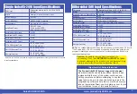
General Specifications
Module Type
Intelligent
Modules per Base
15 maximum*
I/O Points Used
None, mapped directly to tags in CPU
Operating Temperature
0º to 60ºC (32º to 140ºF)
Storage Temperature
-20º to 70ºC (-4º to 158ºF)
Humidity
5 to 95% (non-condensing)
Environmental Air
No corrosive gases permitted
Vibration
IEC 60068-2-6 (Test Fc)
Shock
IEC 60068-2-27 (Test Ea)
Field to Logic Side Isolation
1800VAC applied for 1 second
Insulation Resistance
>10MΩ @ 500VDC
Heat Dissipation
5.76 W
Enclosure Type
Open Equipment
Module Location
Any I/O slot in a Productivity2000 System
Field Wiring
Use
ZIP
Link Wiring System. See “Wiring Options” on page 4.
EU Directive
See the “EU Directive” topic in the Productivity Suite Help File.
Information can also be obtained at:
www.productivity2000.com
Weight
90g (3.2 oz)
Agency Approvals
UL 61010-1 and UL 61010-2-201 File E139594, Canada & USA
CE (EN 61131-2 EMC, EN 61010-1 and EN 61010-2-201 Safety)**
**Meets EMC and Safety requirements. See the D.O.C. for details.
Status Output Specifications
Status Outputs
4 sink/source
Output Signal Type, per Channel Select Current Sinking
Current Sourcing
Operating Voltage¹
5–24 VDC
5–24 VDC¹
Output Volts Maximum
36VDC
26.4 VDC¹
Output Current Maximum
500mA
Overcurrent Protection
Short circuit detect and current limit with automatic retry
for each output
Output Self Limiting Current
1.2 to 2.4 A
Max Inrush Current
Self limited
Output Voltage Drop
0.7 VDC @ 0.5 A
Thermal Protection
Independent over temperature protection each output
Output Voltage Clamp During Inductive
Switching
+45VDC
-20VDC
Maximum OFF to ON Response
25μs²
Maximum ON to OFF Response
25μs²
NOTES:
1. Operating voltage of current sourcing outputs must be no greater than external
power.
2. Measured at 5VDC operating voltage, 0.5 A load current.
Power Specifications
External Power
24VDC -15% / +10%, Class 2
Maximum Voltage
26.4 VDC
Minimum Voltage
20.4 VDC
Current Consumption Excluding Outputs
50mA
Maximum Current Consumption Total of the 4
Status Outputs
2A
Status LEDs
Fault Status LEDs
(F) 1, 2, 3 & 4 (one per status output)
Input LEDs
(IN) 1A, 1B, 1Z, 2A, 2B, 2Z, IN3 & IN4 (one per status input)
Output Status LEDs
(O) OUT1, OUT 2, OUT3 & OUT4
* Note:
For complete system limits, please refer to the “Hardware and
Communication Limits” table in the Productivity Suite Help file, “Hardware
Configuration” topic (P050).
Note:
Top row fault LED’s blinking indicates loss of external power.


