5
Sales 800-633-0405
www.productivity2000.com
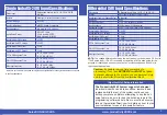
Resolution of Frequency Measurements for “Fast Mode”
Input Frequency
Sampling Period
Resolution
1Hz to 1MHz
1000ms
±1 Hz
10Hz to 1MHz
100ms
±10 Hz
100Hz to 1MHz
10ms
±100 Hz
1MHz
1ms
±1000 Hz
Module Range:
Target position range ± 2.147 billion (32-bit signed integer)
Inaccuracy of Frequency Measurements¹
,
² for “Slow Mode”
Input Frequency
Step/Dir
Quadrature 1X
Quadrature 4X
1Hz
±0.002 Hz
±0.002 Hz
±0.002 Hz
10Hz
±0.009 Hz
±0.009 Hz
±0.009 Hz
100Hz
±0.015 Hz
±0.015 Hz
±0.015 Hz
1kHz
±1 Hz
±1 Hz
±1 Hz
10kHz
±100 Hz
±100 Hz
±100 Hz
100kHz
±1000 Hz
±1000 Hz
±1000 Hz
1MHz
±40000 Hz
±40000 Hz
±40000 Hz
Inaccuracy of Frequency Measurements¹
,
² for “Fast Mode”
Input Frequency Sampling Period Step/Dir Quadrature 1X Quadrature 4X
1Hz
±1 Second
±1 Hz
±1 Hz
±1 Hz
10Hz
±1 Second
±1 Hz
±1 Hz
±1 Hz
100Hz
±1 Second
±1 Hz
±1 Hz
±1 Hz
1kHz
±1 Second
±1 Hz
±1 Hz
±1 Hz
10kHz
±1 Second
±1 Hz
±1 Hz
±1 Hz
100kHz
±1 Second
±1 Hz
±1 Hz
±1 Hz
1MHz
±1 Second
±1 Hz
±1 Hz
±1 Hz
Inaccuracy of Frequency Measurements¹
,
²
,
³
,
⁴ for “Auto Mode”
Input Frequency
Step/Dir
Quadrature 1X
Quadrature 4X
1Hz
±1 Hz
±1 Hz
±1 Hz
10Hz
±1 Hz
±1 Hz
±1 Hz
100Hz
±1 Hz
±1 Hz
±1 Hz
1kHz
±1 Hz
±1 Hz
±1 Hz
10kHz
±100 Hz
±100 Hz
±100 Hz
100kHz
±1000 Hz
±1000 Hz
±1000 Hz
1MHz
±10000 Hz
±10000 Hz
±10000 Hz
1. For stable input signal at given input frequency.
2. For total measurement error add the time base error to the tabulated error.
3. Maximum sample period: 1 second.
4. Minimum sample period: 0.001 seconds.
NOTE:
Refer to the I/O Module Configuration Help File Topic (P212) in the
Productivity Suite Software for more information on Mode selections.
Inaccuracy of Frequency Measurements Due to Time Base Errors
25 MHz Crystal for Time Base
Inaccuracy at 25°C, Maximum
±30 PPM
Inaccuracy 0-60°C, Referenced to 25°C
±30 PPM
Inaccuracy Due to Aging, Maximum
±5 PPM/Year
Max. Time Base Inaccuracy 0-60°C and 10 Years Operation
0.01%
Frequency Measurements


