background image

4

Tech Support 770-844-4200

www.productivity2000.com

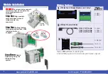
Module Installation

Align

with slot

2

 rotate

to seated

position

WARNING:


Do not apply field power until 

the following steps are completed. See 

hot-swapping procedure for 


exceptions.

Locked

Unlocked

Step One: 

Align module 

catch with base slot and 

rotate module into 


connector.

Step Two: 

Pull top locking 

tab toward module face. Click 

indicates lock is 


engaged.

Step Three: 

Attach 

field wiring using the 

ZIP

Link wiring 


system.

Wiring Options

1

ZIP

Link Feed Through 

Modules and Cables¹

ZL-RTB40
ZL-RTB40-1

       ZIP

Link 

Pre-wired Cables

0.5 m (1.6 ft) cable

1.0 m (3.3 ft) cable

2.0 m (6.6 ft) cable

ZL-CBL40S
ZL-CBL40-1S
ZL-CBL40-2S

3

Accessories²

ZL-RTB-COM

TW-SD-SL-1

TW-SD-MSL-1

2

1.Cable + 

ZIP

Link Module = Complete System

2. ZL-RTB-COM provides a common connection point for power or ground

ZL-RTB-40-1

ZL-RTB40

Содержание Productivity2000 P2-HSI

Страница 1: ...safety problems you should follow all applicable local and national codes that regulate the installation and operation of your equipment These codes vary from area to area and it is your responsibilit...

Страница 2: ...annel Select Current Sinking Current Sourcing Operating Voltage 5 24 VDC 5 24 VDC Output Volts Maximum 36VDC 26 4 VDC Output Current Maximum 500mA Overcurrent Protection Short circuit detect and curre...

Страница 3: ...F to ON Response Time 1A 1B 2A 2B 0 48 s 1Z 2Z 3IN 4IN 6 s ON to OFF Response Time 1A 1B 2A 2B 0 48 s 1Z 2Z 3IN 4IN 6 s Max Input Frequency 1A 1B 2A 2B 1MHz 1Z 2Z 3IN 4IN 200kHz Differential 5V Input...

Страница 4: ...ector Step Two Pull top locking tab toward module face Click indicates lock is engaged Step Three Attach field wiring using the ZIPLink wiring system Wiring Options 1 ZIPLink Feed Through Modules and...

Страница 5: ...Hz 1 Second 1 Hz 1 Hz 1 Hz 10kHz 1 Second 1 Hz 1 Hz 1 Hz 100kHz 1 Second 1 Hz 1 Hz 1 Hz 1MHz 1 Second 1 Hz 1 Hz 1 Hz Inaccuracy of Frequency Measurements for Auto Mode Input Frequency Step Dir Quadrat...

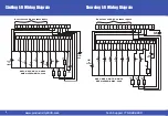
Страница 6: ...w capacitance Dead head shield this end Tie shield to panel ground this end To prevent damage to P2 HSI 5V inputs do not exceed 6 8V or 30 mA on inputs 1A 1A 1B 1B 1Z 1Z 2A 2A 2B 2B 2Z 2Z B C E A 1A 1...

Страница 7: ...C E Sensor Sensor Sinking Field Device Sourcing Field Device 5VDC to 24VDC PWR D S SNK SRC OUT1 LOAD D S SNK SRC OUT2 D S LOAD SNK SRC OUT3 D S LOAD SNK SRC OUT4 LOAD PWR 24VDC 5VDC to 24VDC When 2nd...

Страница 8: ...SNK OUT2 SRC SH SH OUT3 SNK OUT3 SRC 1A 1B 1B 1Z 1Z 2A 2A 2B 2B 2Z 2Z 1A 1A OUT4 SNK OUT4 SRC PWR PWR IN 3 IN 3 IN 4 IN 4 1B 1B 1Z 1Z 2A 2A 2B 2B 2Z 2Z 1A 1A 1B 1Z 2A 2B 2Z IN3 IN4 LOAD OUT4 SRC 24 V...

Отзывы: