


16
NeoSlider™ - Sliding Gate Opener NES-24V1
Owner Installation Instructions
Setting Travel Limits
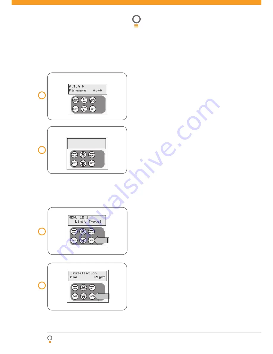
MENU 10.1
Limit Travel
PR E S S
10
fi g
Installing antenna
Mount the antenna at or above the height of the gate
or fence (whichever is higher) for optimal reception. Do
not cut the coaxial cable.
PLEASE NOTE - Before plugging the NeoSlider™
in, check the power cord for damage and ensure it
cannot become entangled in any moving parts
After powering up the NeoSlider™, the controller
will go through a startup sequence displaying the
STARTUP SCREEN
(Fig. 08).
This indicates the
controller type and fi rmware version.
After a short delay the MAIN SCREEN
(Fig. 09)
will
be displayed. If this is the fi rst time the NeoSlider™
has been used, the MAIN SCREEN should indicate
that the limits are not set. If the display shows that the
gate is disengaged or an input is active, then rectify
the situation before continuing with the procedure for
setting the travel limits for a single gate.
Powering Up The Drive Unit
08
fi g
09
fi g
This section shows how to set the travel limits. The
procedure can be partly completed using a transmitter.
In order to use a transmitter, it must fi rst have at least
one of its buttons coded to the gate controller. The
function assigned to the transmitter’s buttons is of no
concern here as the buttons are temporally assigned
to OPEN, CLOSE and SET.
NOTE:
The limit setting
procedure can be aborted at anytime by pressing EXIT.
NOTE:
Gate should be moved manually to fully open
position. When re-engaging opener, nudge gate until
click is heard to confi rm pinion gear has engaged fully.
Step 1. Navigating to “set gate travel menu”
1. Press PREV to navigate to Menu 10
(Fig. 10)
.
2. Press SET to display MENU 10.1.
3. Press SET again to enter the limit setting procedure.
Step 2. Setting the left/right installation
side settings
1. Select left or right installation side by pressing open
button for the correct side
(Fig. 11)
.
2. Press SET to confi rm.
A.T.A N
NES-24V1
Firmware
#.##
, I MI T S
.O T
3 E T
0 R E S S
T O ! C C E S S
-% .53
Start up screen
Main screen
Installation
Side
Right
PR E S S
11
fi g


