I.S. INTERCOM
20-278-12
TYPE ABMA4 USER MANUAL
9 OF 21
Issue: 05
PSA Health Interface Icons
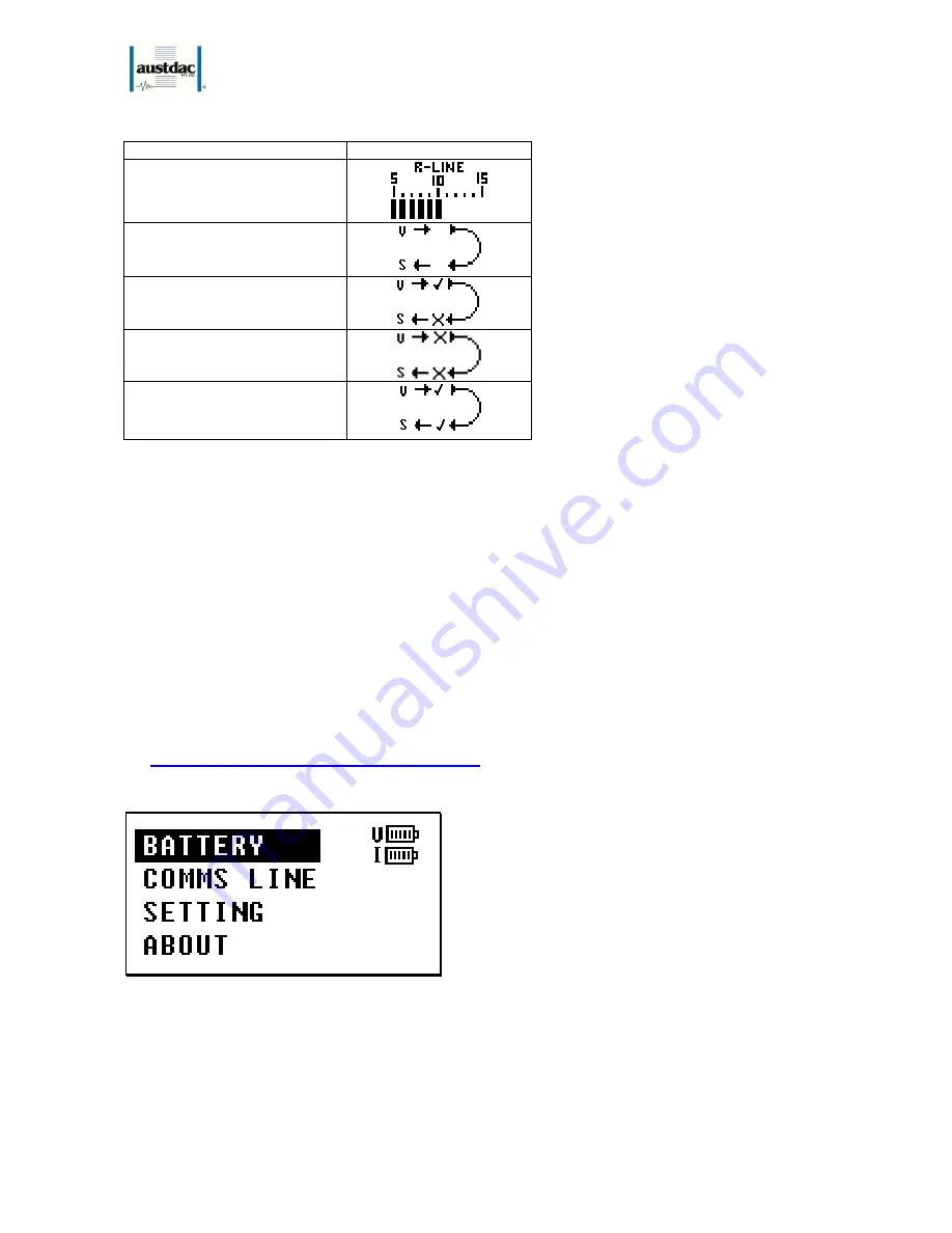
Icon explanation:
Icon:
R-Line bar-graph
Voltage level of R-line at
±
0.5V
resolution
Un-tested PSA loop
See “Comms Line” Menu to see
last confirm state.
Partly working PSA loop
Faulty PSA loop
Fully working PSA loop
Table 2: Top Right Generic Icons
The ‘PSA Loop’ icon flashes when a PSA test is occurring and shows that a change in state may happen.
The flashing will occur a few second after PSA to ensure the user notices any changes especially if it is a
short PSA.
A partly working PSA loop can happen if there is an S-line connection fault or V-line connection fault. If both
lines have a fault, then the unit cannot see the PSA controller and will display an un-tested PSA icon.
See System Test section below.
Text Box
The text box area of the screen provides the user with text information referring to the operation of AMBA4.
For example, it displays ‘SPEAK’ when the speak key is pressed or ‘LOW LINE VOLTAGE’ when the R-line
voltage is low.
5. CONFIGURATION MENU DESCRIPTION
While in Generic Display mode (see Figure 2), pressing the ‘Menu’ key will get the following menu options:
Figure 3: Menu Options
Each Configuration menu option provides either more detailed status information or the ability to change
settings in the ABMA4. To ‘Exit’ the menu display mode, press ‘Menu’. The ‘Menu’ key toggles you in and
out of the Configuration and Generic display modes. To enter a menu option (eg. ‘Battery’) you press the
‘Enter’ key. To move between menu options press the up (
⇑
) or down (
⇓
) keys.


